An introduction to Breadboards
1 Getting stuck in
Try It
- Last lesson you looked at a virtual board, to become familiar with how a breadboard is connected internally.
- We'll now learn how to wire a breadboard so it works, and is neat.
- Ensure you have the following:
- Breadboard,
- Side cutters,
- Wire stripper,
- Long-nose pliers,
- About 15cm of red single-core wire,
- About 15cm of black single-core wire,
- 2x LEDs. Any colour, 3mm or 5mm,
- 2x 330 Ohm resistors,
- 1x 6x6 PTM switch.
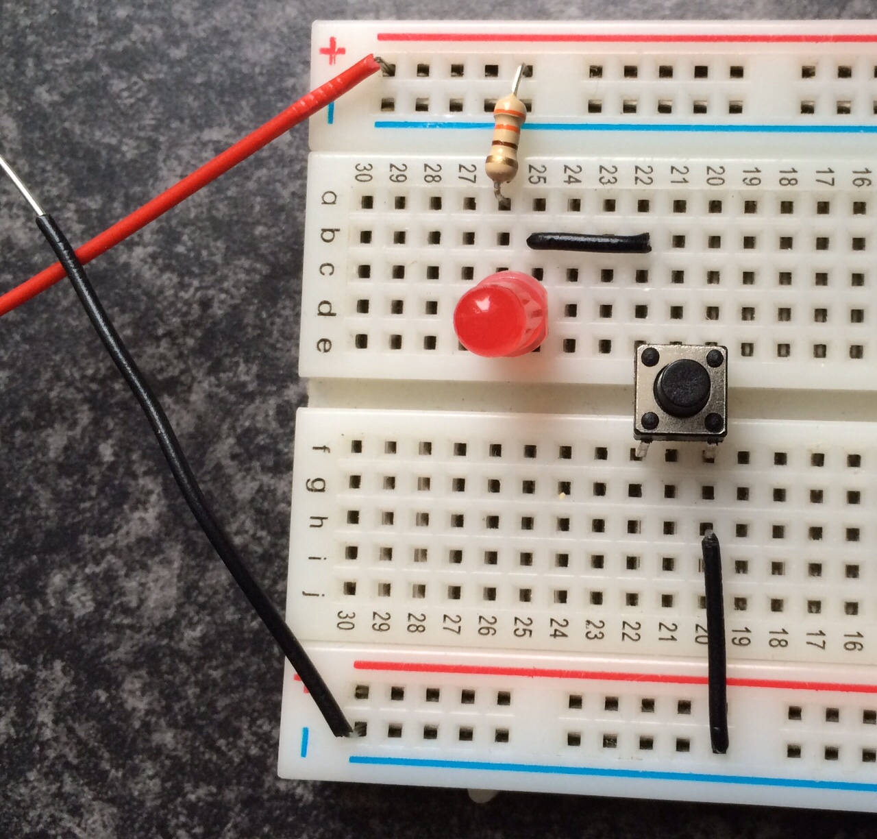
- We'll start with something you're familiar with; the first circuit from the previous lesson.
- Rather than mess around with PP3 batteries (is it flat? Have I got it the right way around? Why aren't there enough batteries, etc), we'll power or circuit with a plug-in DC power supply that runs on the mains.
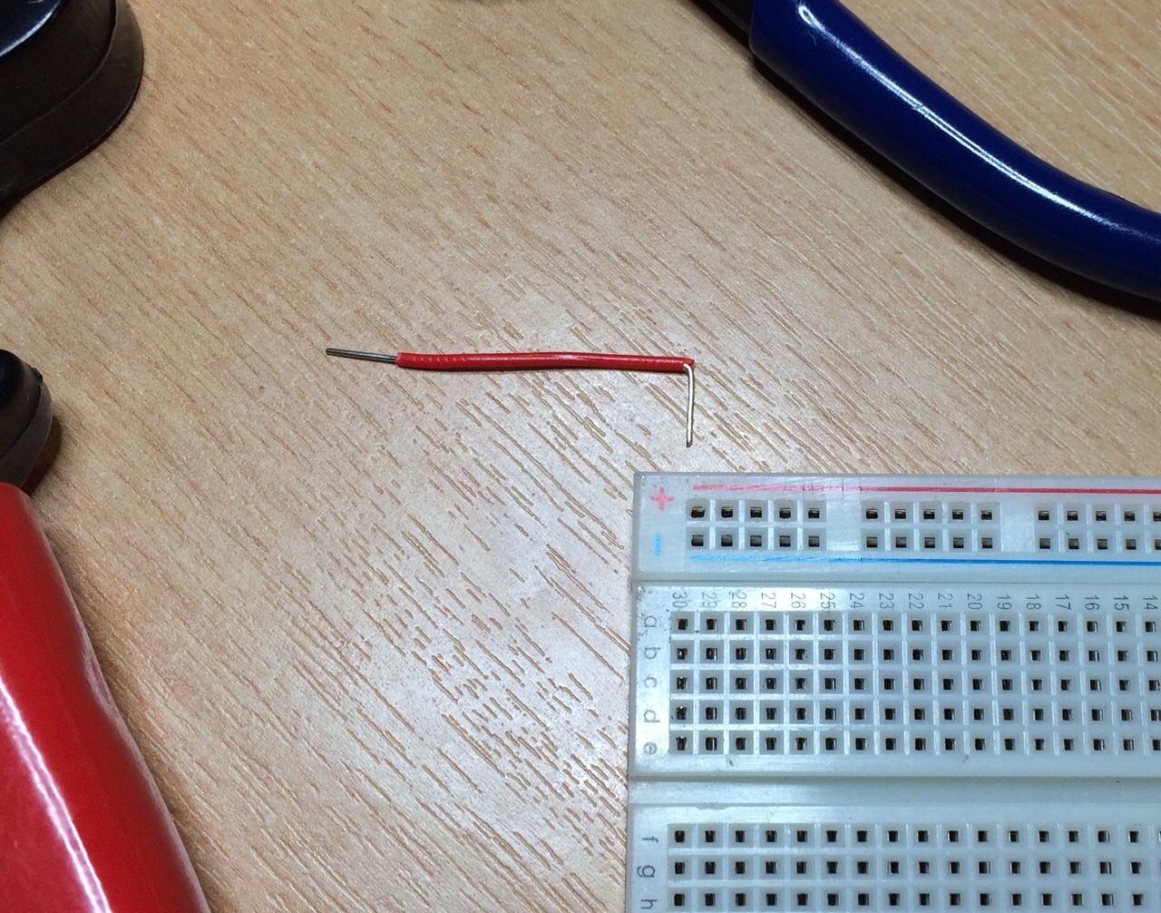
- Take a short (e.g. 5cm-ish), and strip around 5mm of insulation from both ends.
- Use a pair of long-nose pliers to bend one of the stripped ends by 90 degrees. While it's tempting to bend it with your fingers, you won't be able to get the bend as neat.
- Put the bent end in the top-right hole, and leave the remaining wire hanging off the end of the board.
- Repeat this with a piece of black wire, putting it in the very bottom-left corner hole.
- When we want to test our circuit (once its built), we can just attach the red crocodile clip to positive, and the black to negative.
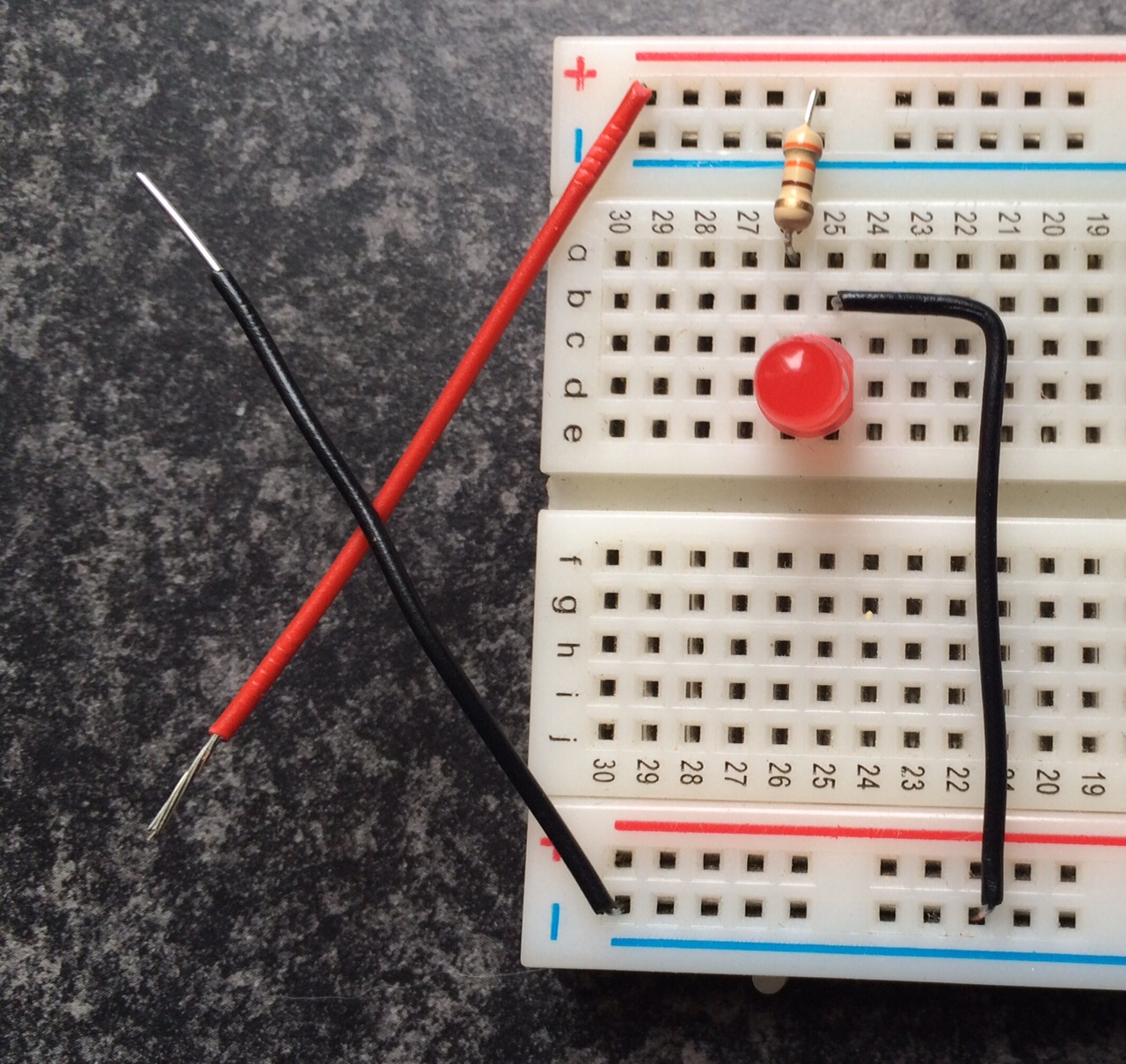
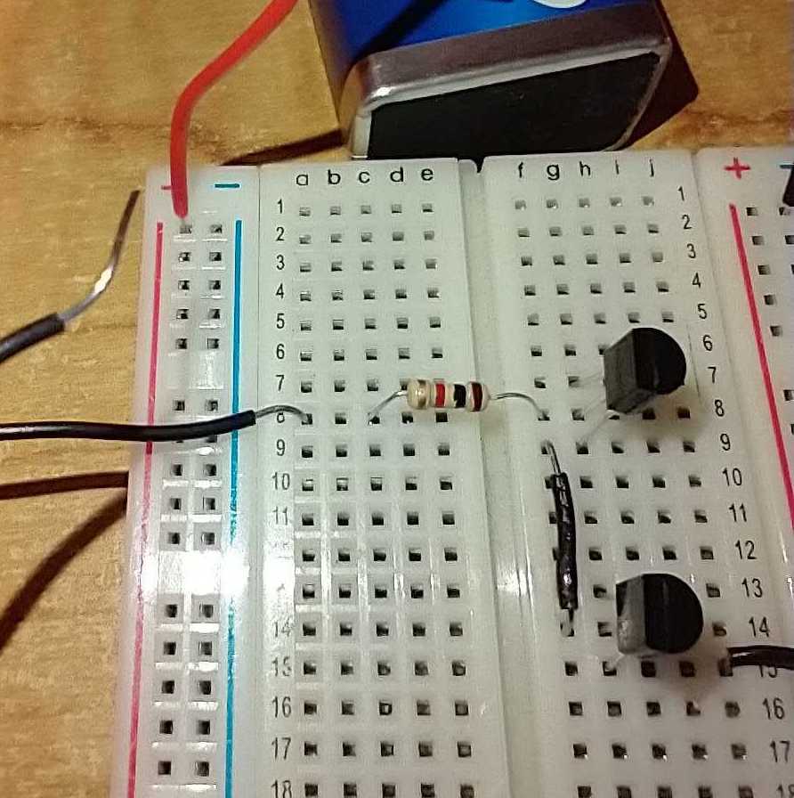
- By carefully trimming and bending the legs of your resistor, you can fit this flat to the breadboard as per the diagram above.
- Trim the legs of your LED so they have about 7mm protruding (remember that the negative leg of the LED has a flat edge on its body).
- Finally, carefully measure and bend (with long-nose pliers) a piece of black single-core wire to neatly take it to the bottom row.
Try It
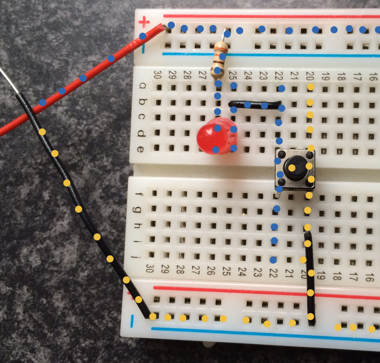
- We'll add a PTM switch to the board, so that we've got the same circuit that went into our LED torch at the start of the year.
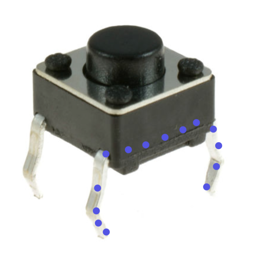
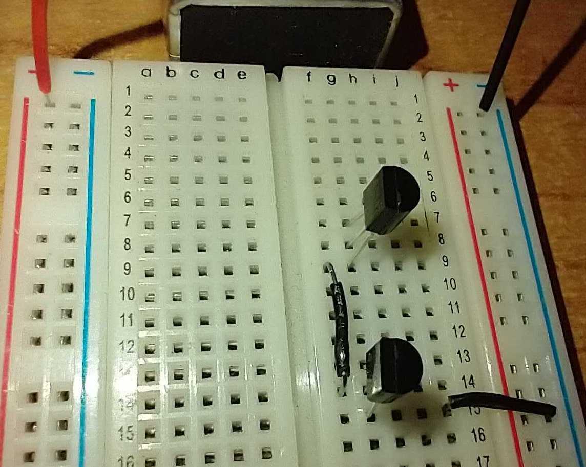
- Fetch a 6x6 PTM switch from the component racks, and take a moment to look at it.
- These switches are made by having two hoops of metal side by side, with a gap between them. One of the hoops is emphasised in the picture above.
- When the button is pushed, a short piece of wire touches both hoops, closing the switch and allowing current to flow from one hoop to the other.
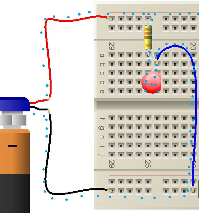
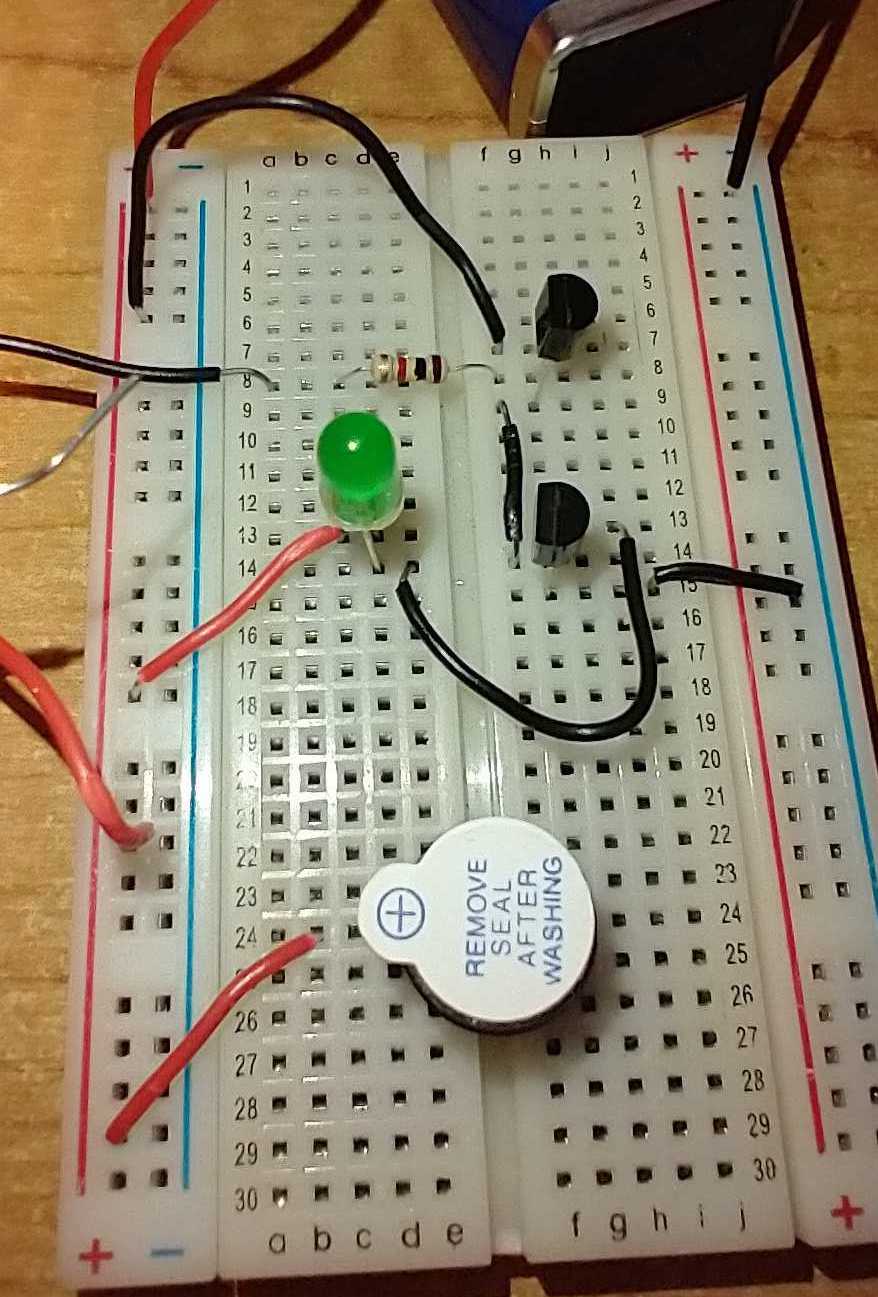
- Modify your circuit to include the switch, as shown below. The centre of a breadboard is designed to take components like chips and switches. You need to ensure that the switch is the right way around (so that the hoops in the switch run vertically).
- Connect it to power, and give it a try!
- The diagram below shows the circuit before the PTM is pushed (shown in blue) and the additional connections when the switch pushed (orange).
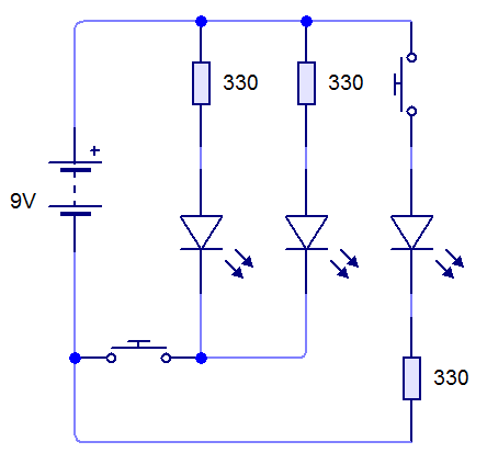
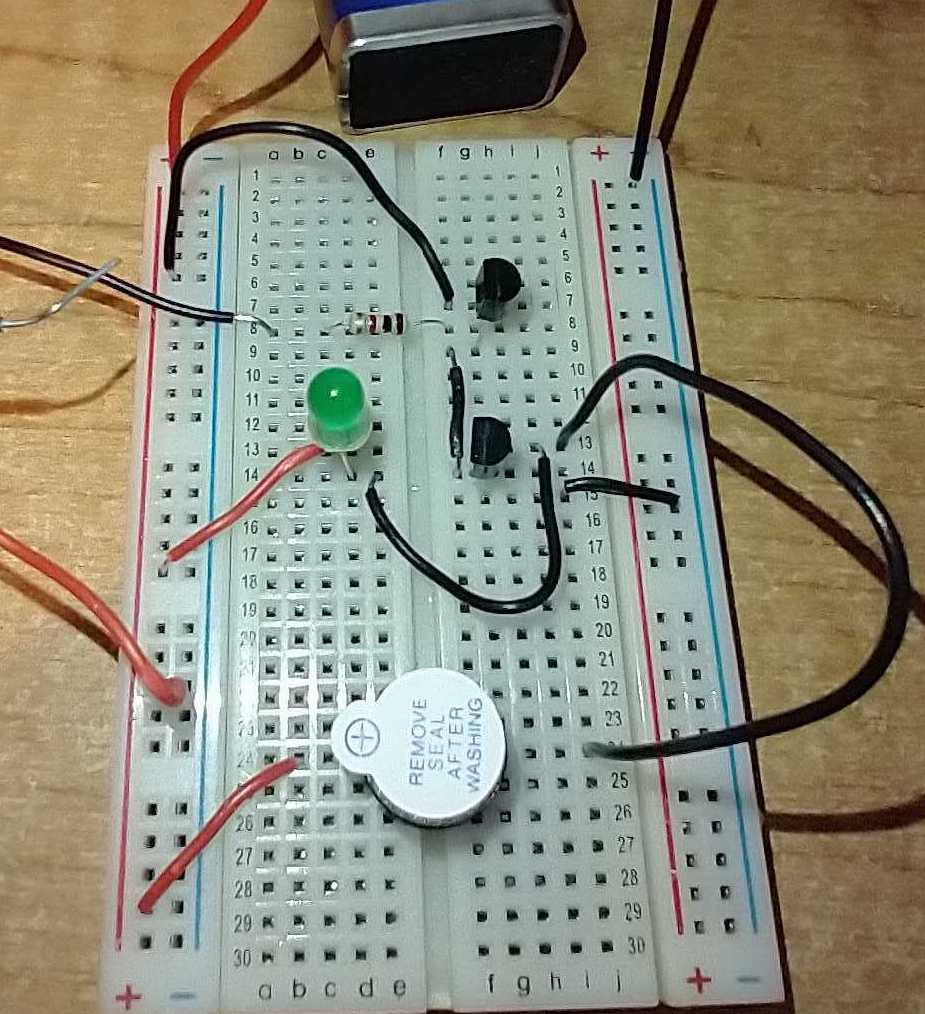
Badge It - Silver
- Create this circuit on a breadboard, and take a picture of it.
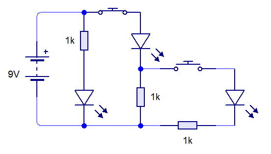
Badge It - Gold
- Create this circuit on a breadboard, and take a picture of it.