An introduction to Breadboards
1 Breadboards
Learn It
- In the early days of electronics, people realised that sometimes it is desirable to be able to create a temporary circuit, without needing to solder parts together, trim their legs and own an PCB etching facility costing several hundred pounds.
- One day, an electronic engineer took a wooden breadboard, and hammered lots of rows of nails into it. To build circuits, short pieces of wire were wrapped around different nails, causing them to be electrically connected, and components could then be soldered to the wires, forming circuits.
- Modern bread boards use a similar idea, but with rows of connected metal contacts inside a plastic case rather than nails. By pushing components into different rows, a complete circuit can be formed.
2 Getting acquianted
Learn It
- In this unit, you're going to create some circuits on breadboards.
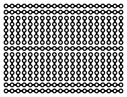
- ("Breadboard scheme" by Breadboard-144dpi.gif: en:User:Waveguyderivative work: McSush (talk) - Breadboard-144dpi.gif. Licensed under CC BY-SA 3.0 via Wikimedia Commons.)
- If you break a breadboard open, this is that you'd see inside. Essentially, lots of little strips of wire. We'll start by designing a 'virtual' breadboard on the computer, then you'll make the real thing.
Try It
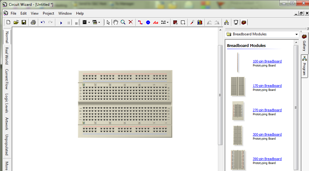
- Open up Circuit Wizard 3 and click File -> New
- Double-click Breadboard Circuit from the list of options; it's towards the bottom.
- On the right-hand side of the screen that appears, click on a 390-pin breadboard, then click in the middle of the screen to place your board.
- Select the breadboard, and use the keyboard shortcut Ctrl+R to rotate it until the thin red line on the outermost edge is at the top of the screen.
- You're now ready to build a circuit!
- We'll start by building a cut down version of your LED torch.
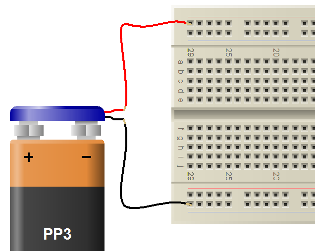
- Start by grabbing some power. There's a PP3 battery with clip, located in Offboard Components -> Power Supplies at the bottom of the list. Place this to the left of your breadboard, and by clicking and dragging from the red (positive) terminal of the battery, connect to the top-left corner hole of the breadboard. Connect the black (negative) battery wire to the bottom-left corner.
- You've now got power on your board. Current can flow along the red wire from the battery, then once it arrives at the breadboard, it can flow to all the holes in the top row of the breadboard.
- This isn't a complete circuit though. Electrons can't get to the negative end of the battery, and the circuit doesn't actually do anything yet.
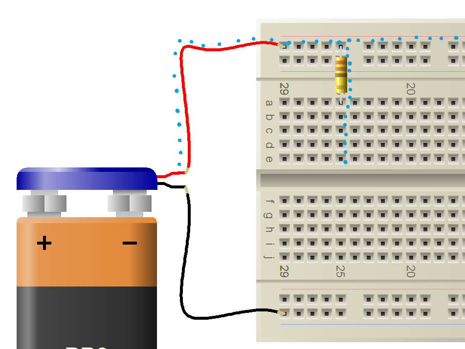
- Add a 10.2mm 330 Ohm resistor to the breadboard, so that one leg is running from any of the holes on the top row into one of the columns below it.
- The current now has the option to travel through the resistor, so that it arrives in the vertically arranged column shown above.
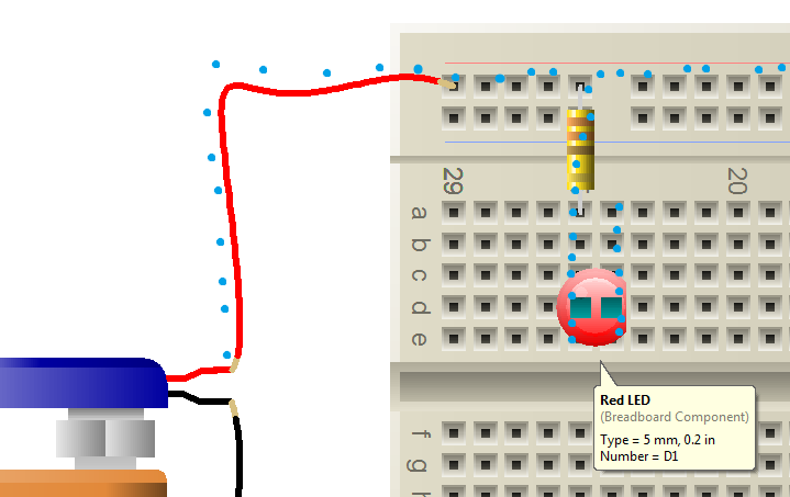
- To complete our circuit, we need to add a 5mm LED. Don't forget that the curved edge of the LED (on the left-hand edge in my picture above) is the positive leg, and should be in the same column as the bottom of the resistor. The dots I've drawn now show that the current has a continous, unbroken route it can take from the battery, through the resistor and through the LED. We're nearly finished.
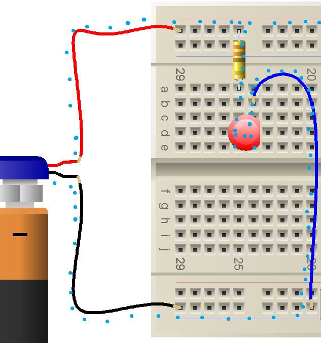
- By clicking and dragginin one of the empty holes above the negative leg of our LED, we can draw on a wire to take us to the bottom of our breadboard and on to the negative end of the battery.
- Click the 'Play' icon at the top of the Circuit Wizard window to see your work - the LED should light up, showing you've made the board correctly.
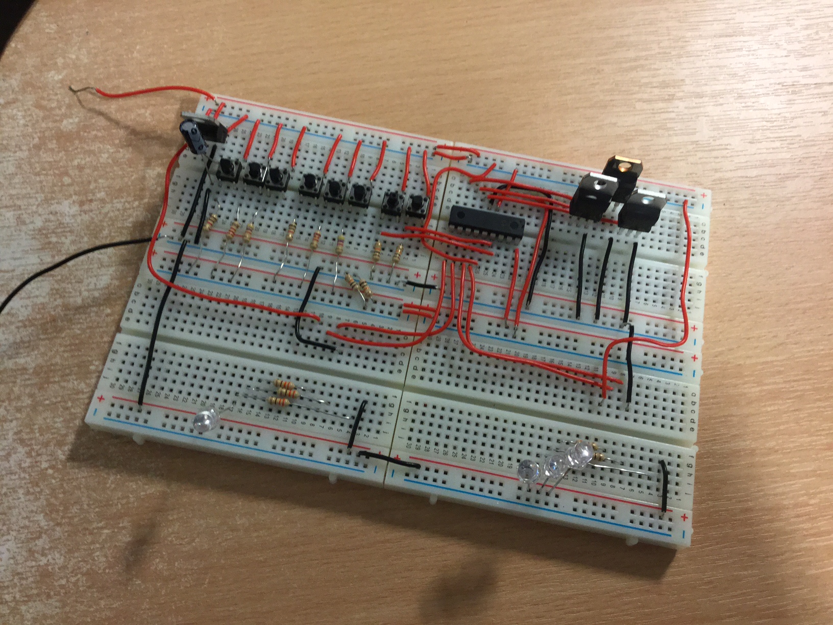
Badge It - Silver
- Create the circuit above on an actual breadboard using a resitor and an LED.
- Take a photo and upload your work to www.bournetolearn.com
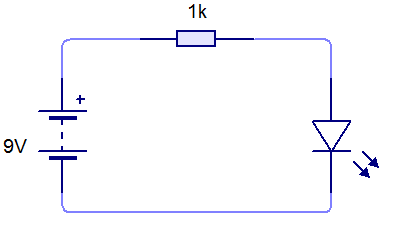
Badge It - Gold
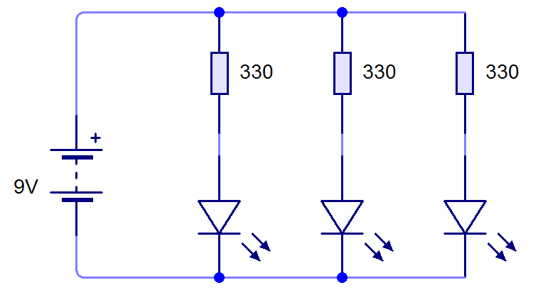
- Recreate the circuit below on an actual breadboard.