BGS Marble Run
1 Introduction
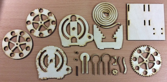
- Below are all the parts you will need to create your own Marble run.
- You can find the template for the laser cutter on the open drive:
- G:\Design Engineering\Reference\Marble Run
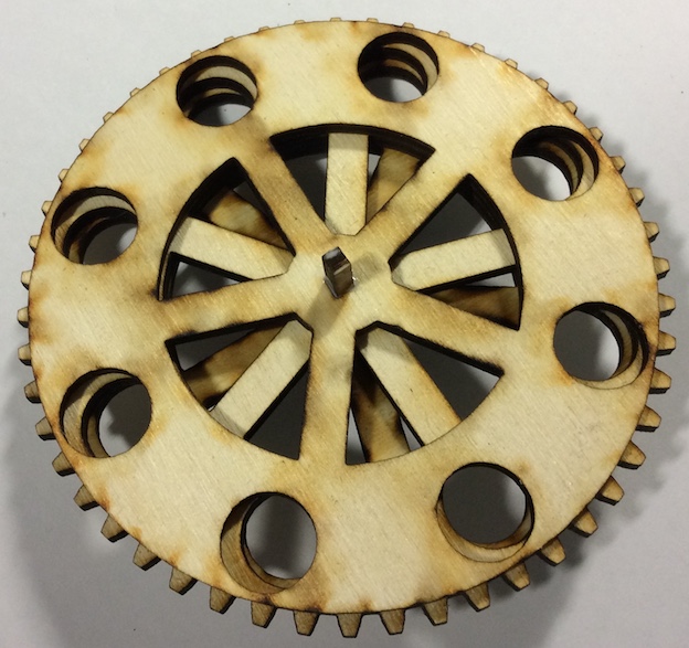
- From the parts, we are going to start with the wheel.
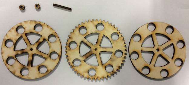
- Collect these parts.
- You will need to put some PVA glue along the centre shaft and then feed it through the wheel starting with the one end and then adding the centre and the other side.
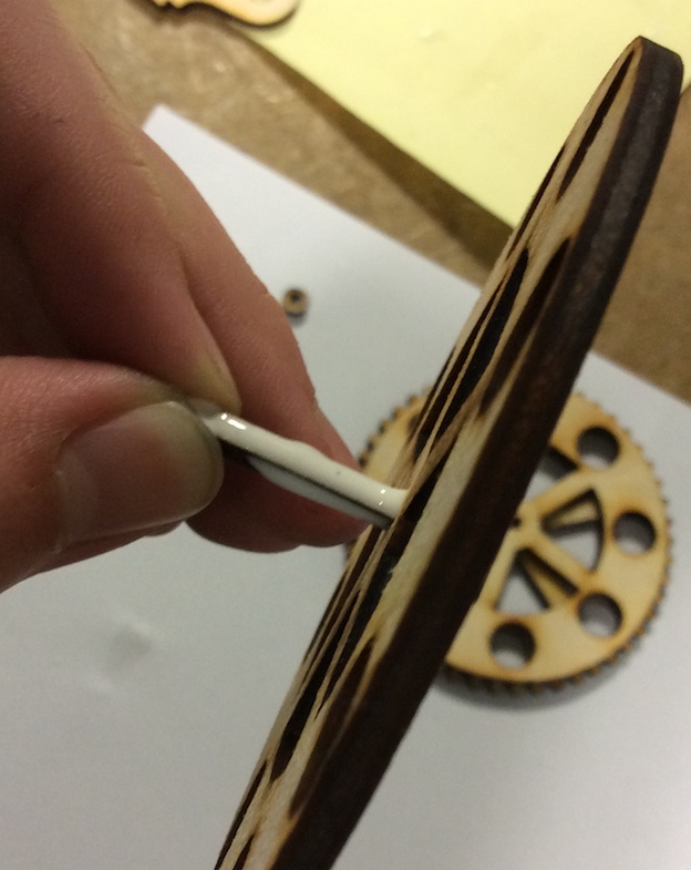
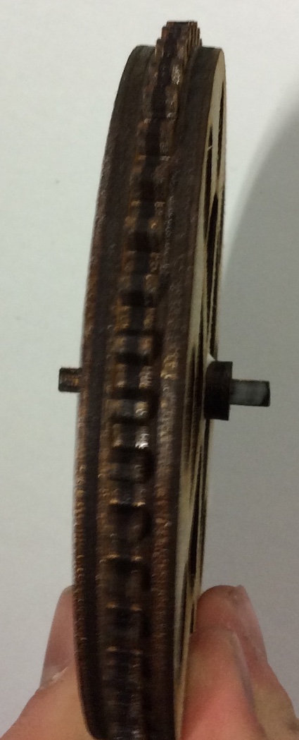
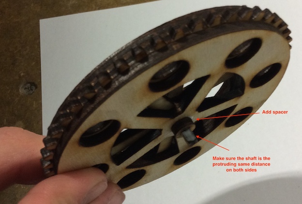
- Now you will need to add the 2 spacers either side making sure the shaft is centred.
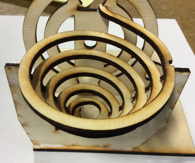
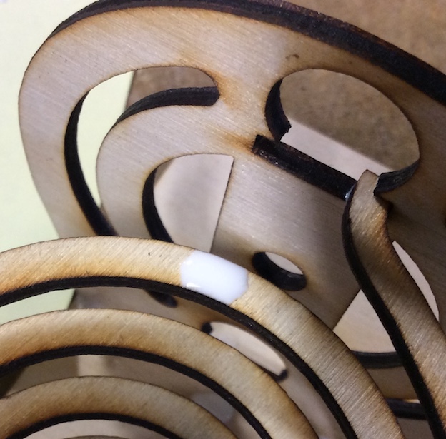
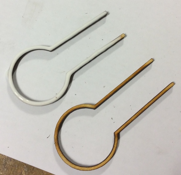
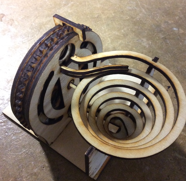
- You will now need to get these part, you will now make the spiral.
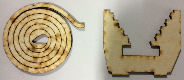
- Push out the spiral GENTLY and then glue it in place, as shown in the fugure.
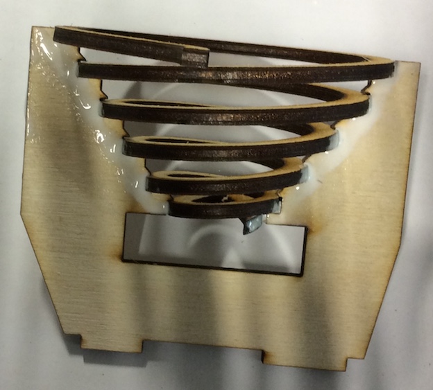
- Leave the glue to dry, we can now start putting togehter the frame.
- Get these parts.
- Glue the upright to the base.
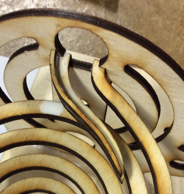
- You can now add the spiral (once it has dried) to the base.
- Glue the top of the spiral to the upright.
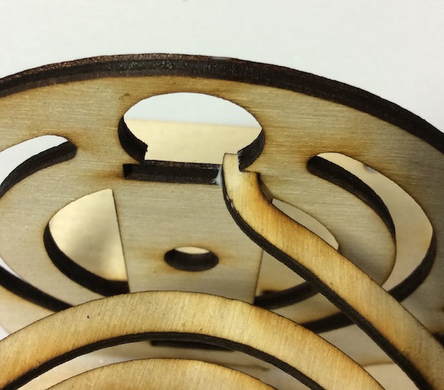
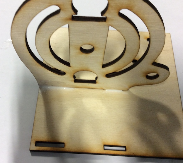
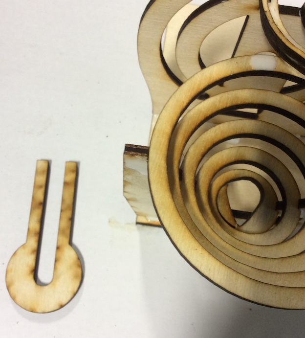
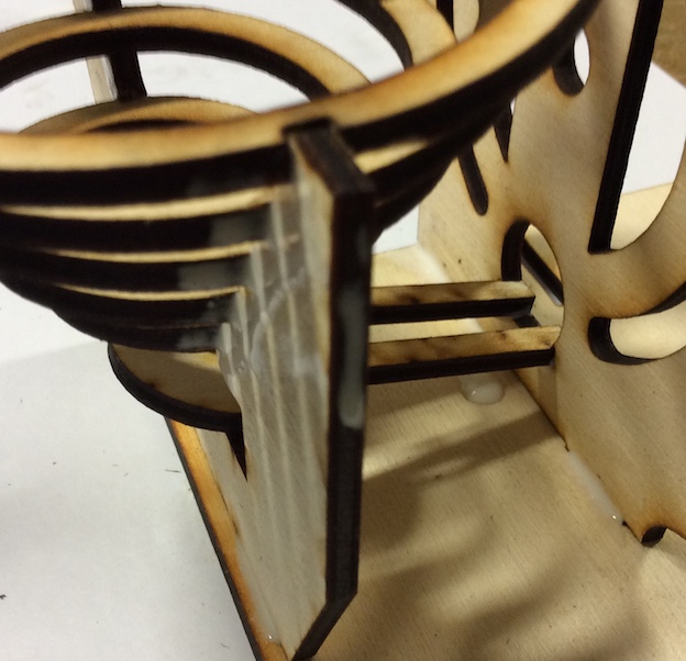
- Now you can make the guide at the top of the spiral.
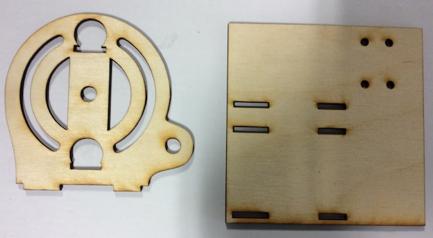
- Get the following parts.
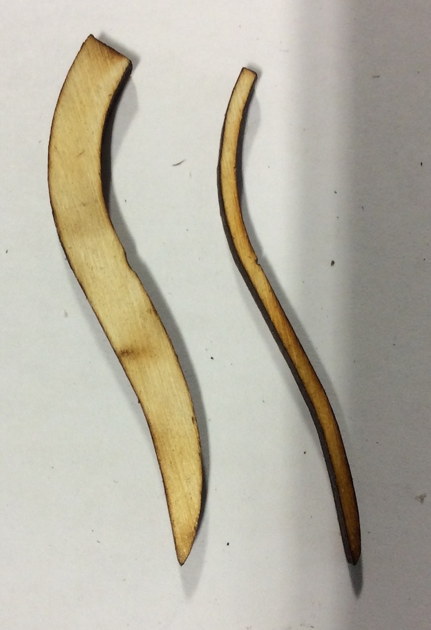
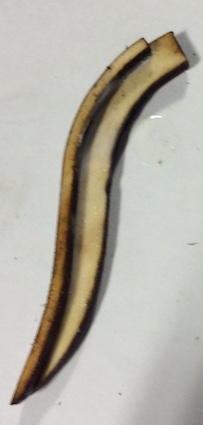
- Glue the thinner piece on top of the thicker one as shown below.
- Now place a small anout of glue on the top of spiral.
- Place the guide on top of this.
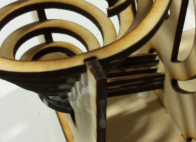
- We are now going to put the guide at the bottom in place.
- Add the guide to the bottom of the spiral and upright.
- The following parts need to be glued on top of the bottom guide.
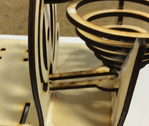
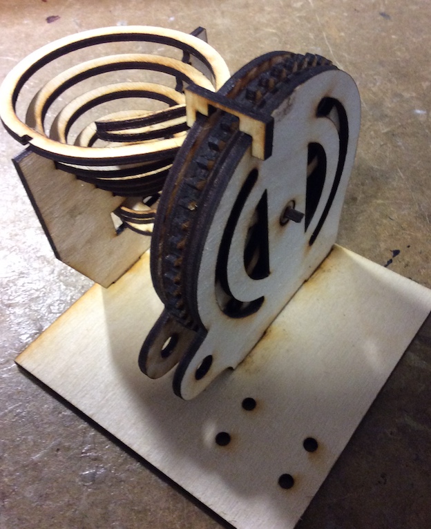
- You can now glue in the opposite upright and then place the support on top of the 2 uprights.
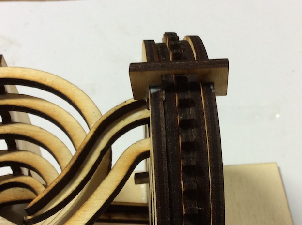
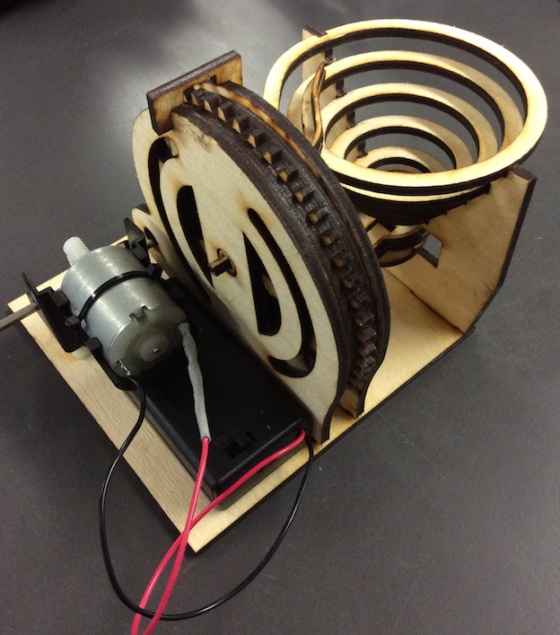
- This is what the moving parts looks like.
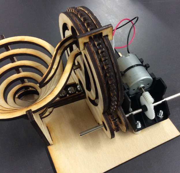
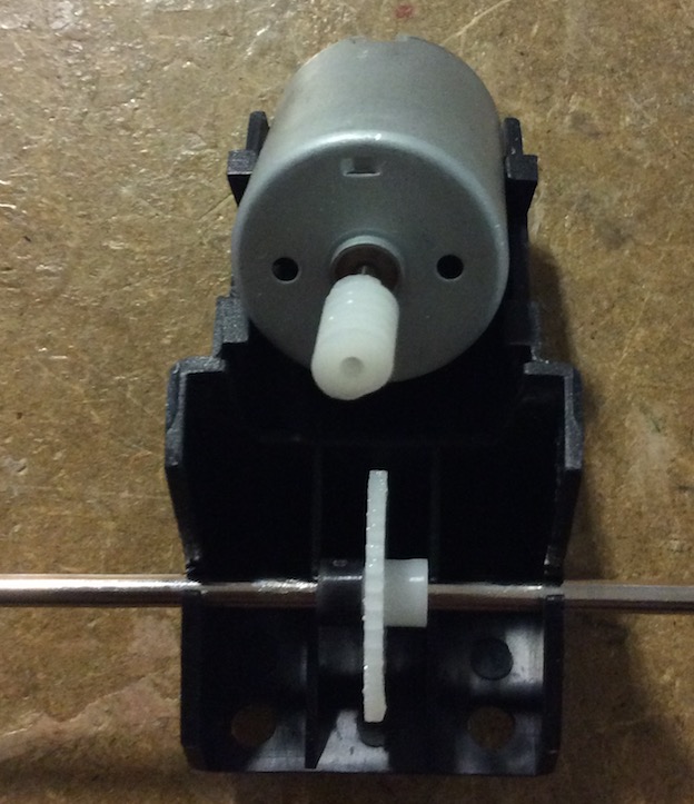
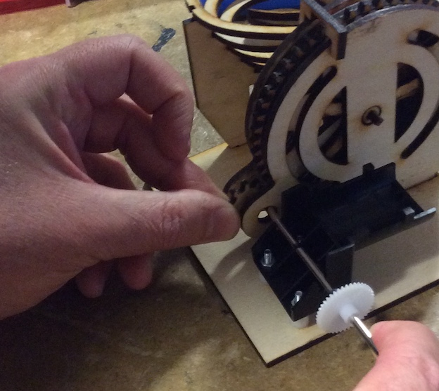
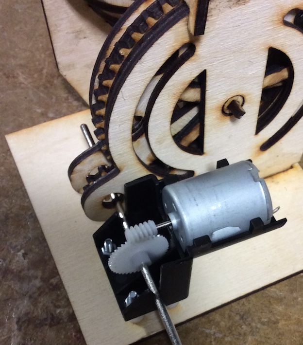
- Now we are going to attach the motor.
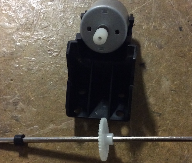
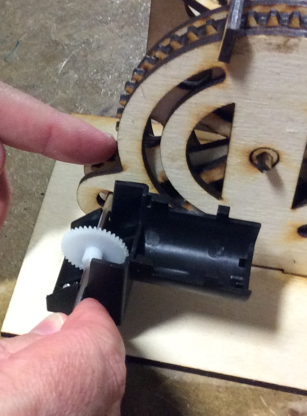
- You will need to removed the motor and the drive shaft from the housing.
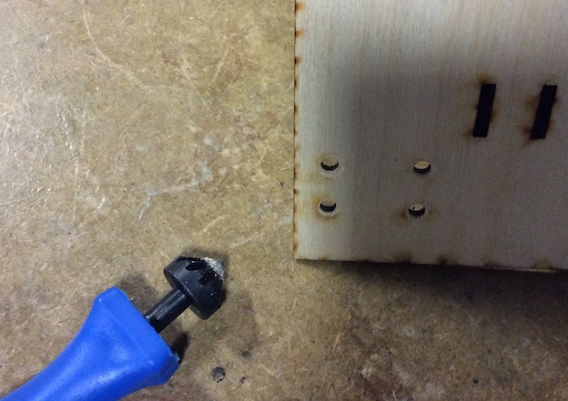
- You will then need to countersink the bottom of the product (the base) to fit the countersink screws.
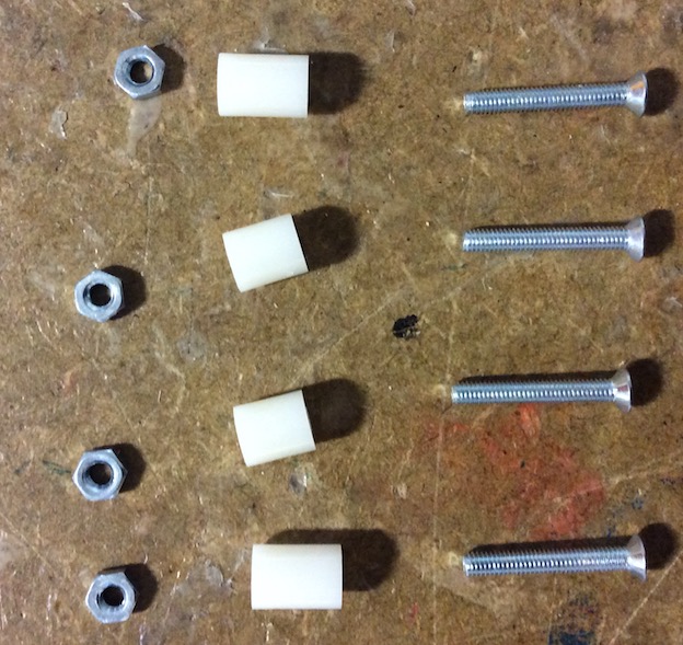
- Collect the M3 X 15mm screws and 5mm plastic spacers along with the M3 nuts (4 of each)
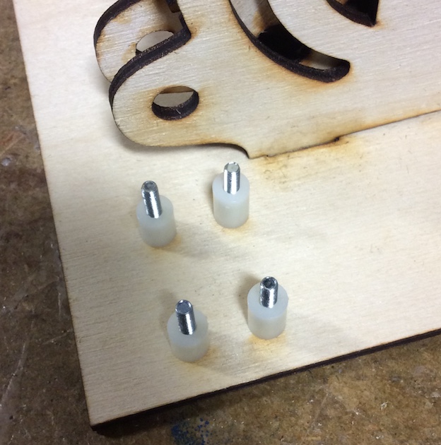
- Push the screws through the bottom and place the 5mm spacer on top of this.
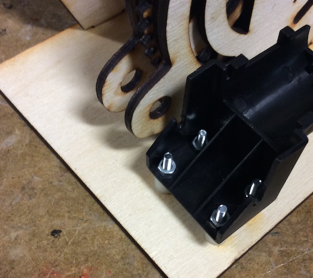
- Next place the motor housing on top of this and then screw it down.
- You will need to use long nose pliers to hold the back nuts in place.
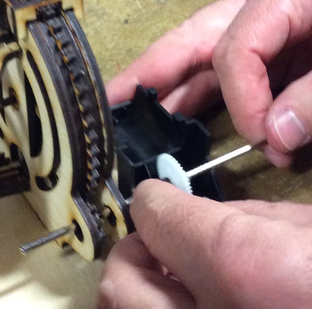
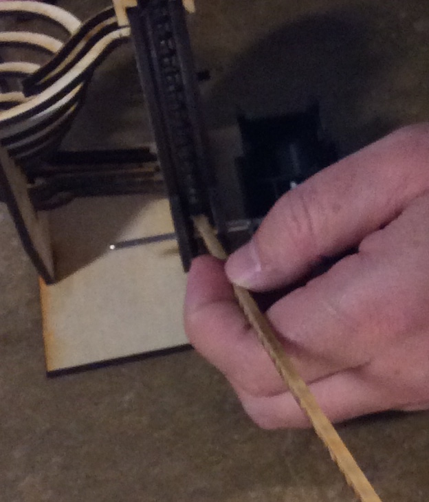
- You will now need to feed the shaft through the drive gear and motor housing connecting it in place.
- We will now need to prepare some epoxy glue.
- Start by squeezing out equal measurements of resin and hardner onto a piece of paper.
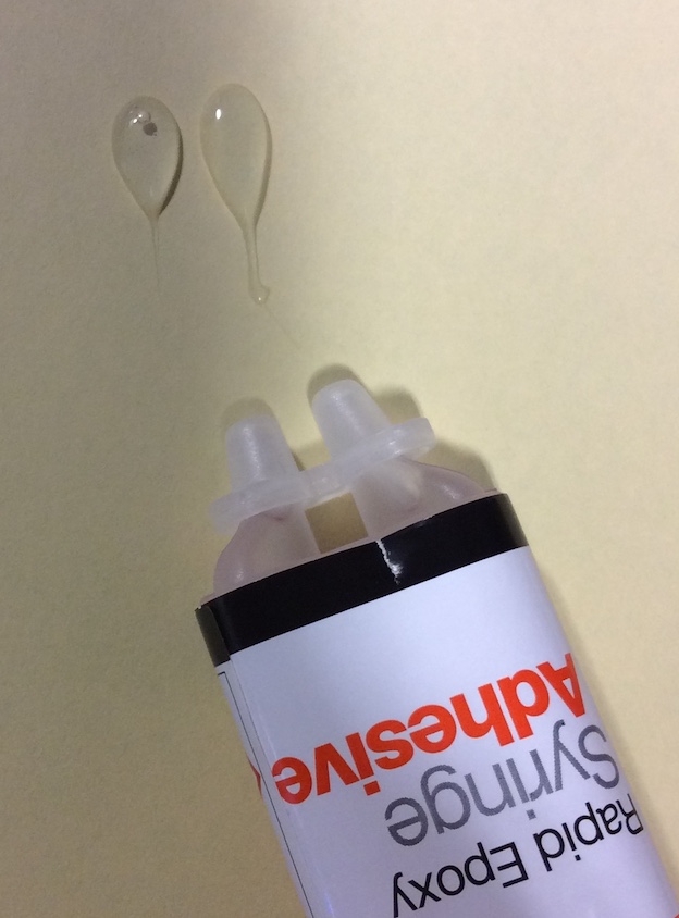
- You will now need to mix them together well, mix for at least 1 minute.
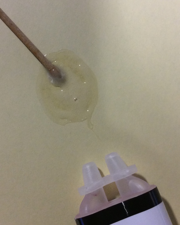
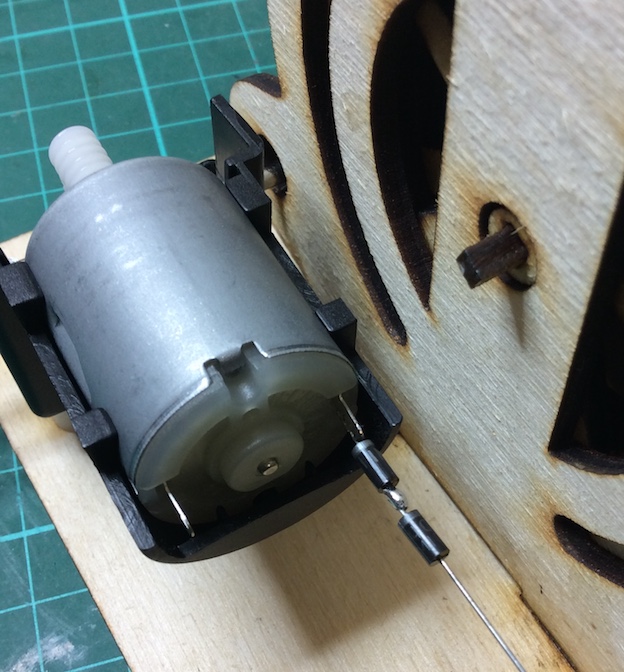
- Place the glue onto the drive shaft and pinion gear, make sure no glue goes into the gears itself.
- Once you have glued this in place, you will need to leave it for 24 hours to harden.
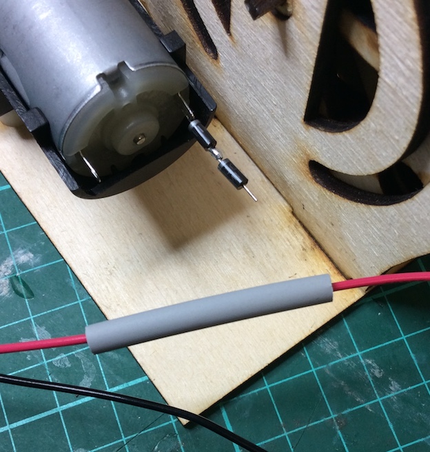
- You will need to solder two 1N4001 rectifier diodes onto the positive terminal of the DC motor.
- Place some grey heatshrink onto the positive (red) wire and the solder in place.
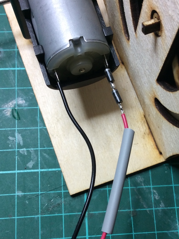
- Now use the soldering iron to shrink the heatshrink.
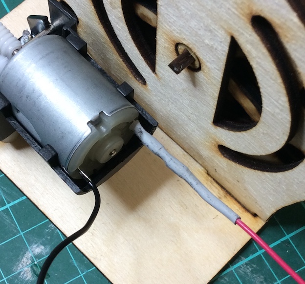
- Your marble run is now ready to go.
- Place 3 to 4 marbles into the run and turn on the switch.