| Lesson 1 | Lesson 2 | Lesson 3 | Lesson 4 | Lesson 5 | Lesson 6 | Lesson 7 | Lesson 8 | BBL Tasks | Achievements |
The Soldering License
1 Introduction
Drill it
- Before you can create the next Martian lander, we'll need to cover some basics on soldering, component identification and multimeter usage.
- Around three quarters of the problems students have with their circuits are down to poor soldering, or inserting components incorrectly.
- This project will help you develop these skills, and at the end, you'll have a PCB which you can use to show how good you are at soldering neatly.
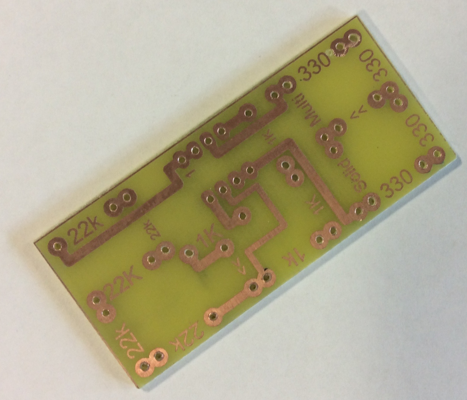
- Once you've collected your soldering license PCB from your teacher, the first thing to do is make sure the track are shiny and clean. Use some steel wool to clean it if necessary.
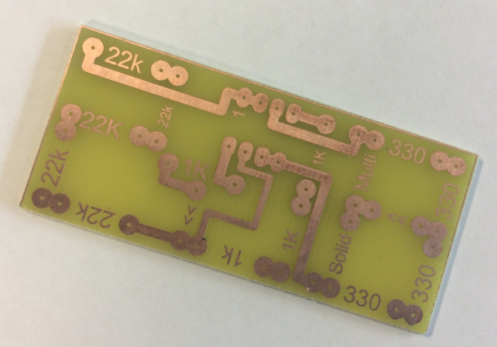
- Then, using a 1mm drill-bit in one of the precision drills, drill out all the other pads on the PCB. Take care to drill through smoothly, and try to get as close to the centre of all the pads as possible. This will make things much easier for you when you start soldering if you do this well.
Solder it
- Time to solder your first component. Plug a soldering iron in, ensure you're wearing an apron and goggles and that any long hair is tied back. The iron will take about 5 minutes to warm up.
- Before starting to solder, lets watch a video familiarising ourselves with the tools available.
- Wet the sponge under the tap, and wring it out, so it's damp but not dripping.
- Take a Rectifier diode from the component trays, and look at it closely. Some components need to be inserted a certain way round, like this diode, which only allows electric current to flow through it in one direction.
- The grey band on one end is like an arrow-head, indicating the direction of current-flow. There's also an arrow on the PCB between two of your holes. This is where the diode needs to go.

- You will need to bend the legs at 90 degrees to push it through the board.
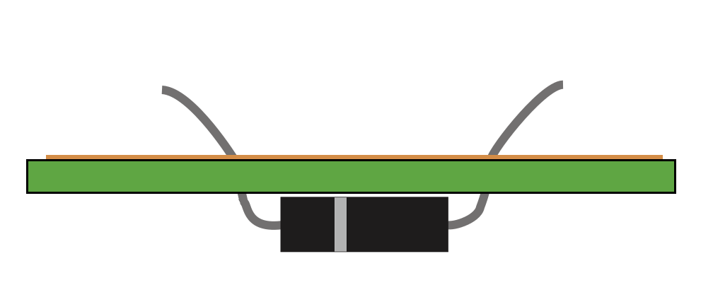
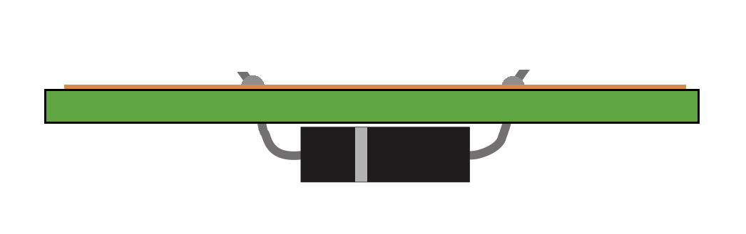
- Place your diode through the holes, so that the grey band points the same way as the arrow-head below the board.
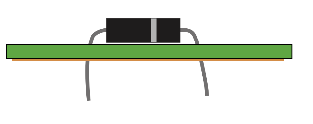
- You then need to turn the board over and then bend the component legs slightly over (30 to 45 degress) to stop it falling out when you solder it.
- DON'T LAY THE LEGS DOWN FLAT AGAINST THE BOARD.
- When soldering, the top of the board (the side with nothing on it) is called the "Component side", and is where all your components will sit when you're finished.
- The side with all the shiny tracks and pads drawn on it is called the "Solder side", and is the side we apply solder to.
- First, place the soldering iron on the component leg and track, the flat edge of the iron should be against the component leg.
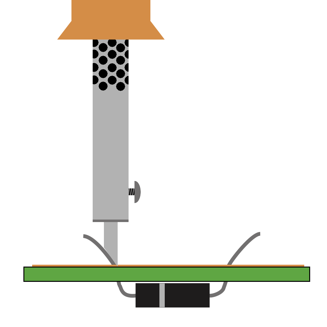
- The solder then needs to be introduced from the opposite side.
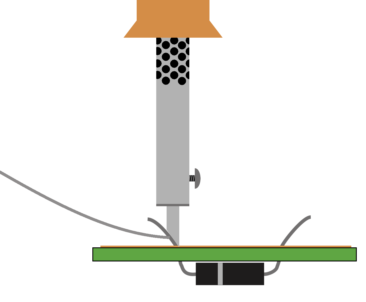
- Add a little solder to the joint until the solder seals the hole and is all the way around the component leg. Be careful not to put too much solder.
- You must always remove the solder wire before the soldering iron.

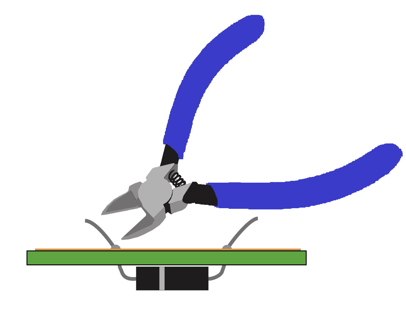
- You now need to use the side cutters to cut the excess wire off.
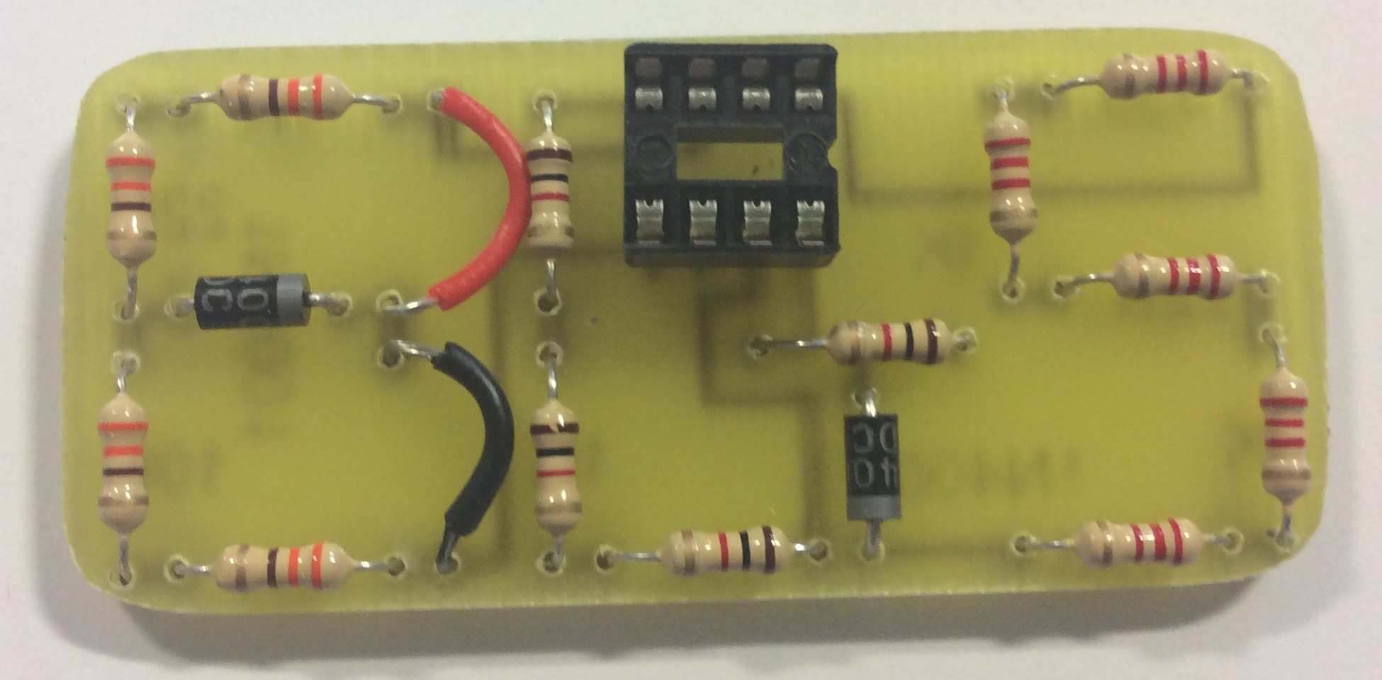
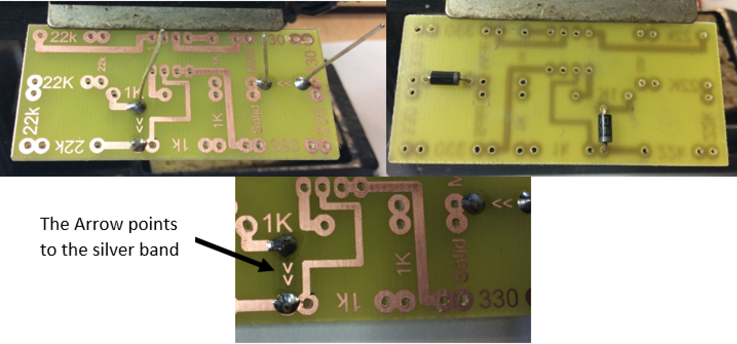
- The finished joint should look like this.
- Here is what the final soldered joints should look like.
- The aim of soldering is to join two metals together; in this case, the metal on the pad on the PCB and the component leg. To achieve this, both surfaces must be heated up for a few seconds, then solder can be melted which will flow on to both metals.
- Here is a video of basic soldering skills.
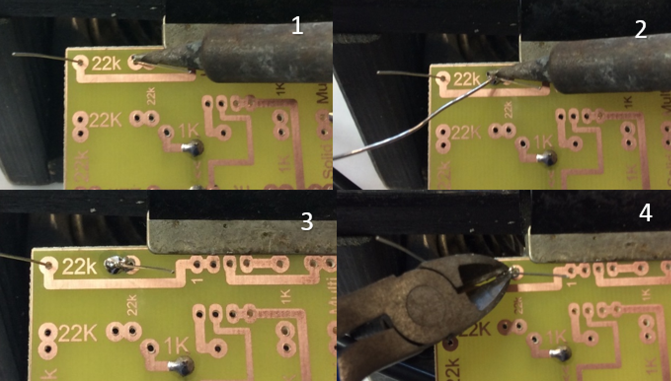
- Step 1: Place the tip of the soldering iron so that it is touching both the pad and the component leg. There is a flat edge on most irons which can be pushed against the leg, so that the very tip of the iron can make contact with the pad.
- Step 2: Count 3 seconds in your head, then (keeping the soldering iron in place) feed in a small amount of solder at the tip of the soldering iron. As long as the pad and leg are hot, the solder should flow onto the PCB nicely.
- Step 3: Slowly remove the solder, then slowly remove the soldering iron, in that order. There should be a neat "mountain" of solder covering both the pad and the leg. The hole inthe PCB should no longer be visible.
- Step 4: Use a side-cutter to remove the excess leg sticking out of the board. Picture 4 shows a couple more components placed, too - we'll add these in a moment.
- Here is another video on soldering from Manchester University.
2 Components
Learn it
- You'll use lots of different components in Design Engineering.
- It's quite important to be able to know which ones are which.
- For one of your badge tasks, you'll need to go online and independently research some of the most common components.
- All electronic components that you'll use have what are called circuit symbols. These are simple drawings that allow experienced engineers to share circuit designs with one another.
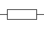
- This is the symbol for a resistor, for instance.
Badge it
- To complete the badges you will need to click on the link at the bottom and complete the quiz. This will automatically badge your work.
- You will need to be logged into www.bournetolearn.com to complete the badge.
- Click on this link components quiz
3 All about resistors
Learn it
- Resistors are probably the most commonly used components in our projects. The purpose of a resistor is to reduce the flow of electrical current in a circuit. They can be set up to reduce the voltage too, but we'll look at that in another module.
- Resistance is measured on Ohms - the larger the number of Ohms, the less current can flow through a circuit.
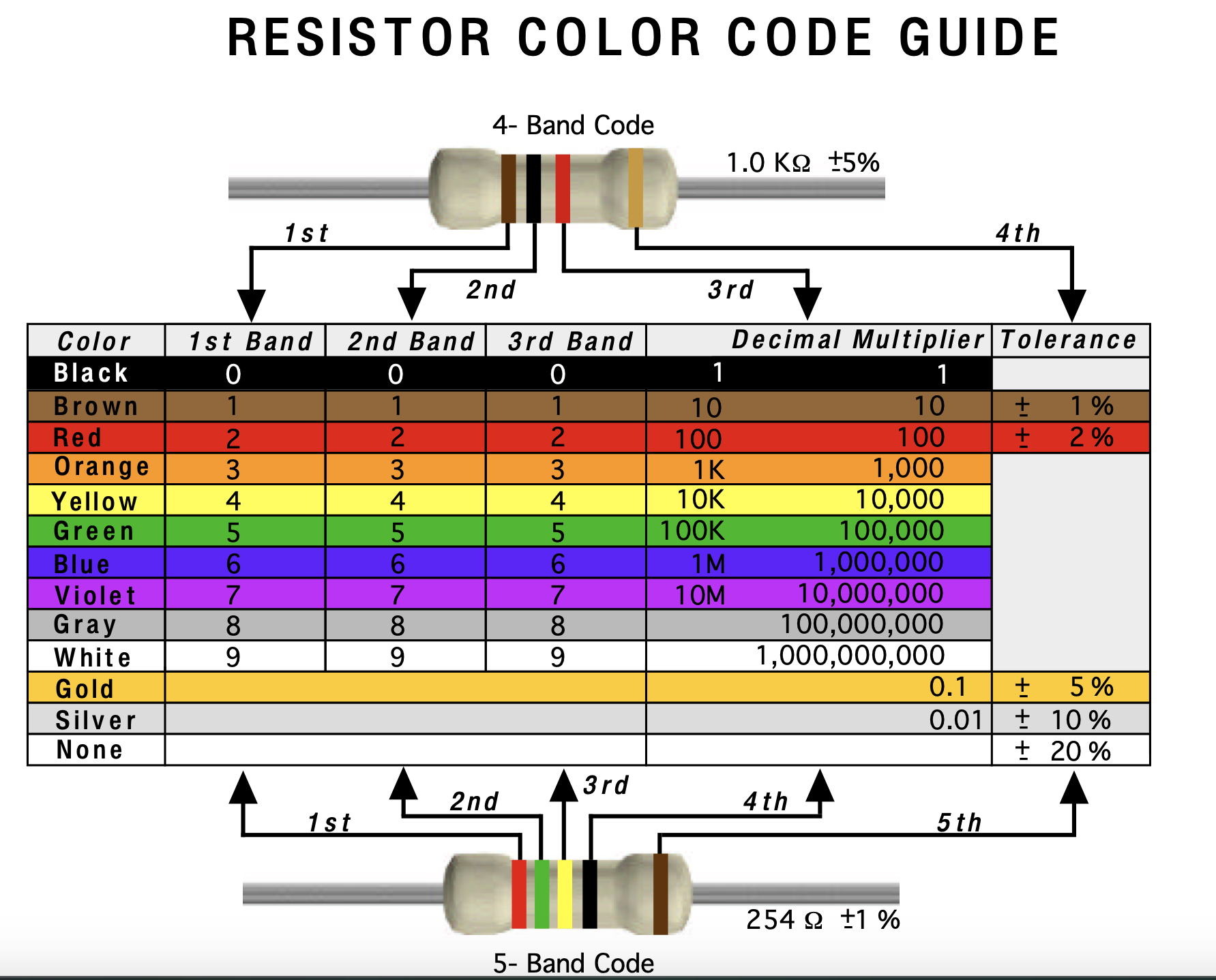
- As the components are small, engineers realised a long time ago that writing the value of the resistor on the component wasn't practical, so instead they developed a system using coloured bands. We'll look at this now.
- When you hold a resistor in your hand, have the gold band facing right. The gold band indicates that these are high-quality resistors, which are accurate to +/-5%. If they had a silver band, they'd only be +/-10%.
- The colour scheme more or less follows the colours of the rainbow, but with some quirks.
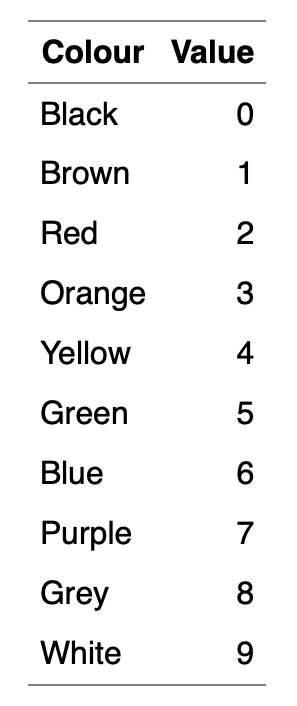
- I use a rather rubbish mnemonic to help me remember: "Black is zero, Brown is 1, then Richard Of York Gave Battle Purple"
- So black is 0, brown is 1, Richard (Red) is 2, Of (Orange) is 3…
- You very rarely see grey and white banded resistors, so I don't have them in my mnemonic. If you can come up with something better, let the teacher know, and you could find your idea featured on BourneToInvent.com!
- To read a resistor, you start by writing down the value for the left-most coloured band.
- You then write the value of the next coloured band next to it.
- The third band tells you how many zeros to write after that. Let's do some examples…
- Orange (3), Orange (3), Brown (0), Gold - 330 Ohms
- Brown (1), Black (0), Yellow (0000), Gold - 100000 Ohms
- People recognised that sometimes, it'd be nice to have a shorthand to avoid writing out lots of zeros.
- Rather than writing a number like 10,000, electronic engineers tend to knock off the last 3 zeros and write 10k instead.
- Rather than writing 2200, people can also write 2k2. You'll see this quite a bit when you look at the component racks in the classroom.
- In the next step, we'll add resistors.
4 Badge It
Badge it
- To complete the badges you will need to click on the link at the bottom and complete the quiz. This will automatically badge your work.
- You will need to be logged into www.bournetolearn.com to complete the badge.
- Click on this link resistor colour code quiz