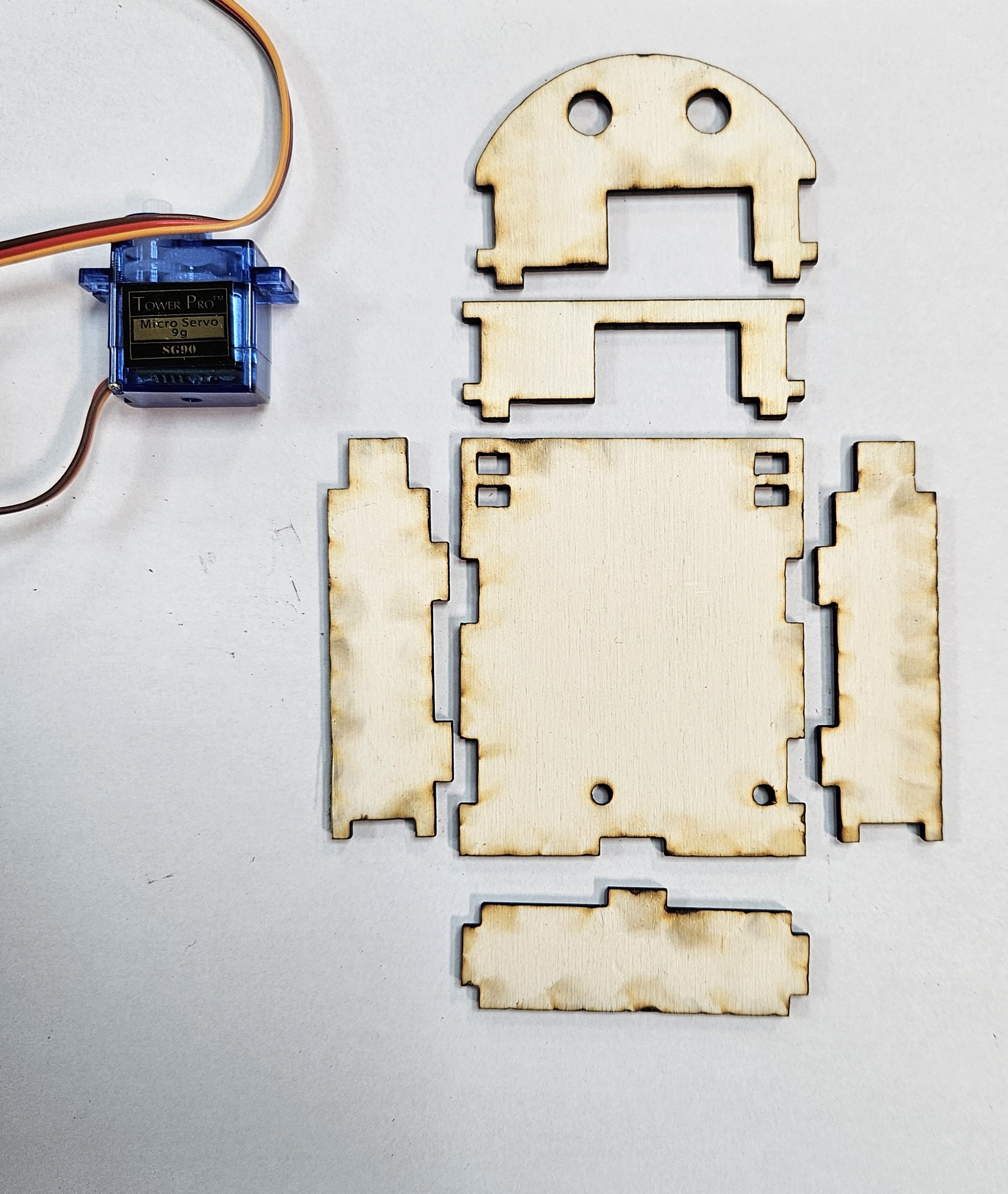
Here are the components you'll need to assemble the Digital Thermometer.
First, you will need to following parts. Please note, you will need the servo motor for this.
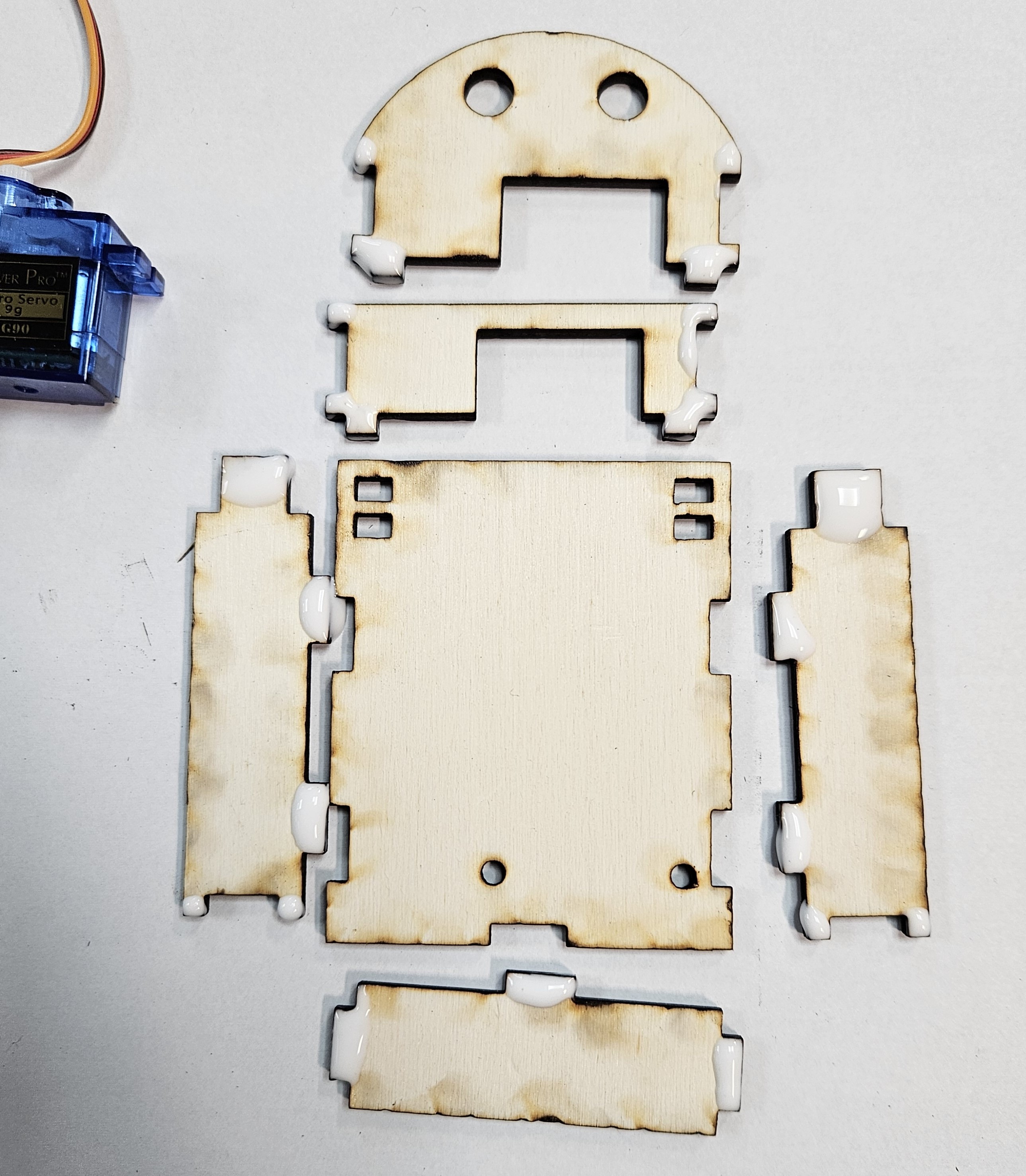
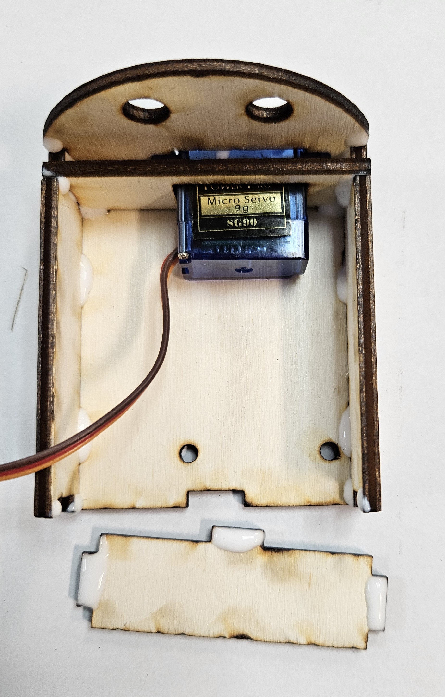
You will now need to add glue as shown.
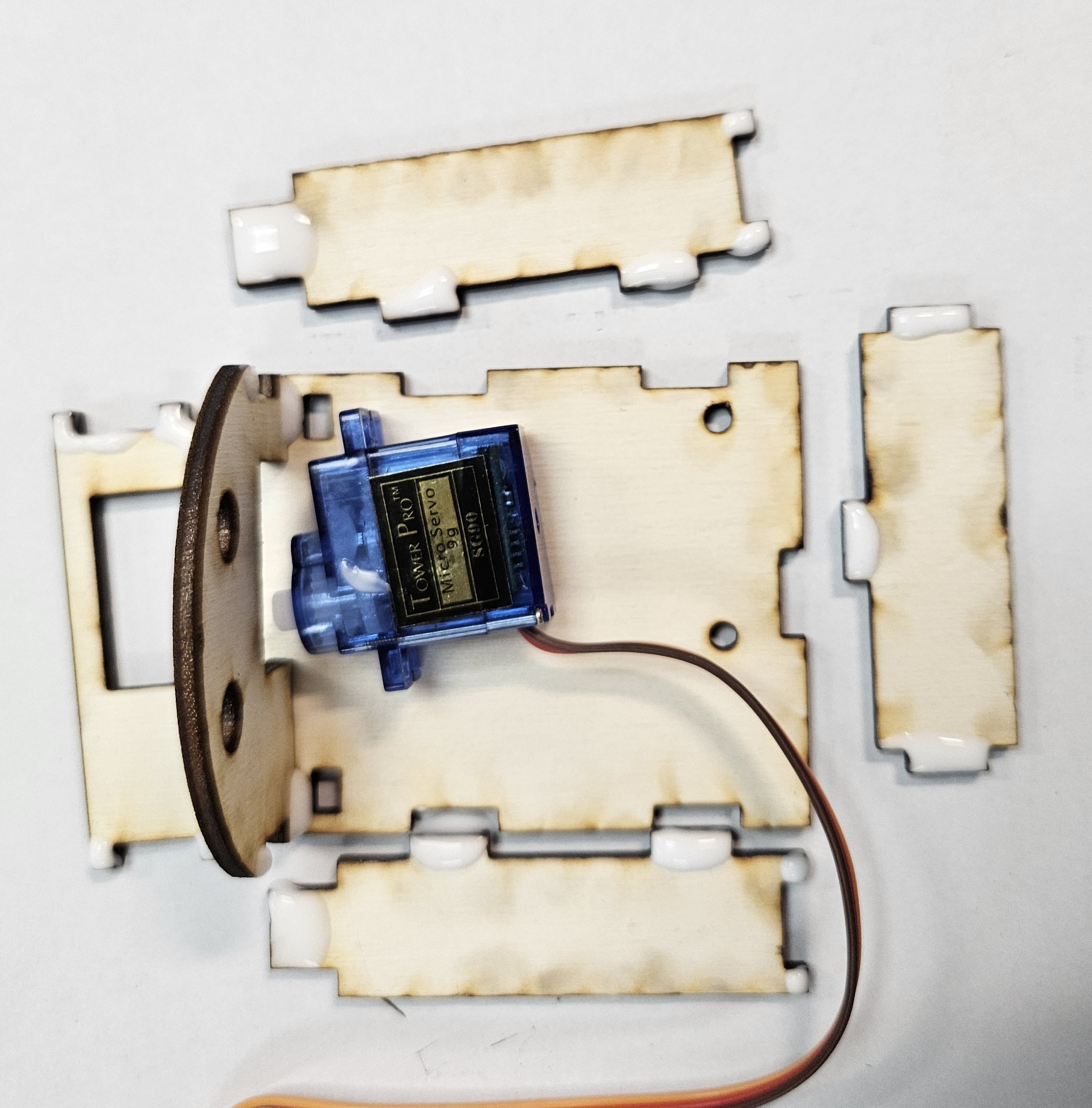
Now place the front panel in place and then place the servo motor in place.
This will need to be left alone for the glue to dry.
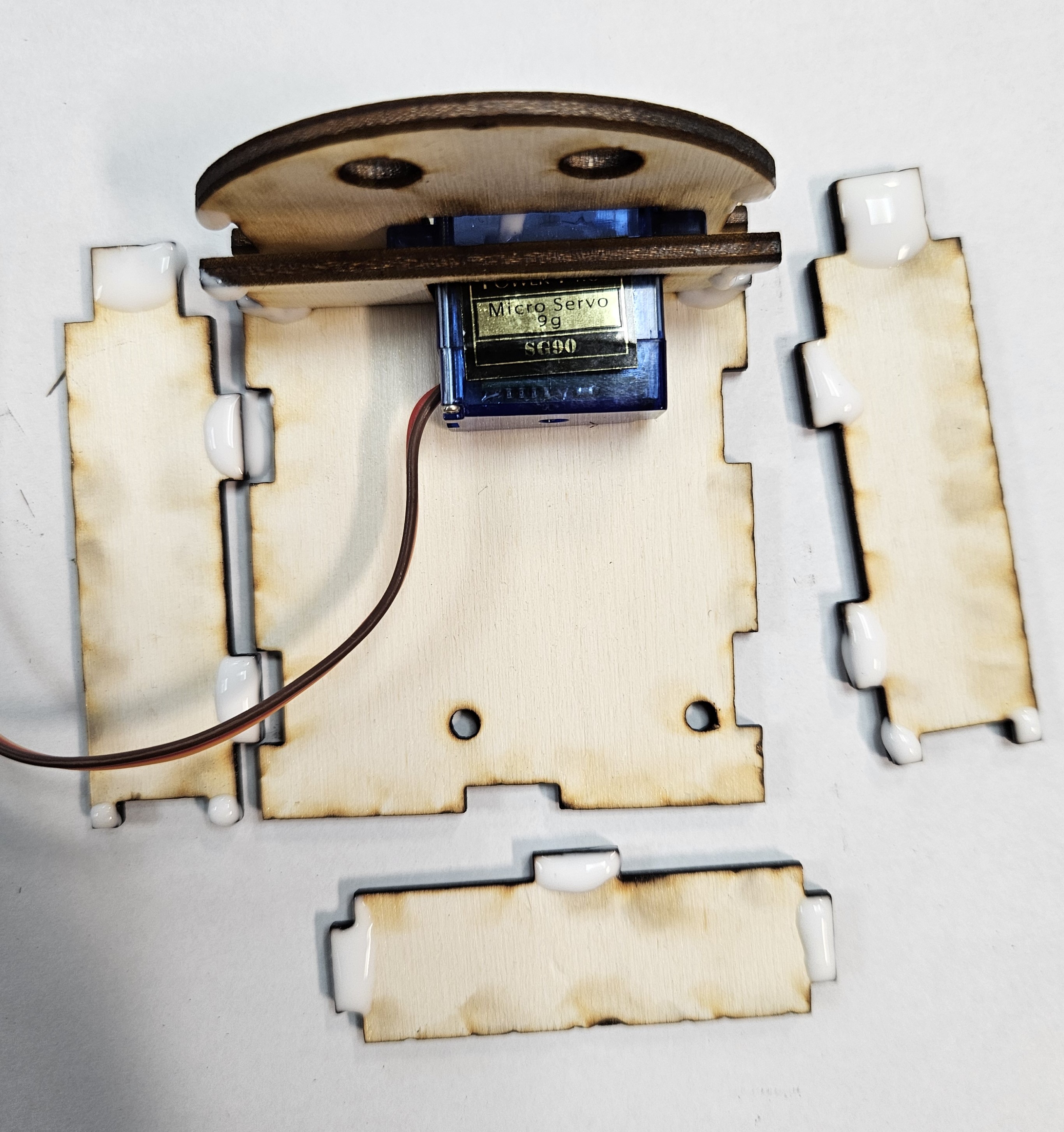
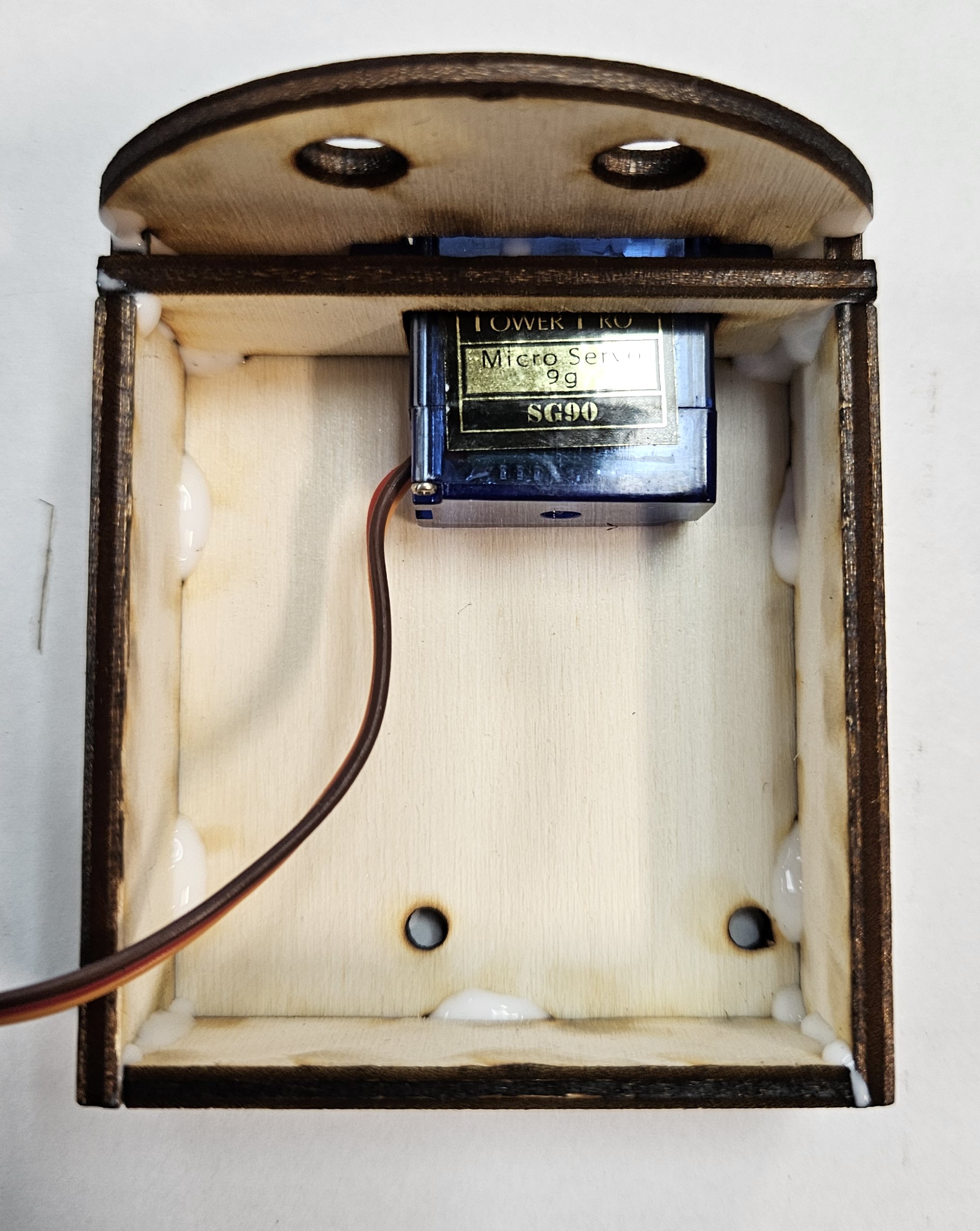
Once the glue is dry, you can now start fitting the servo motor.
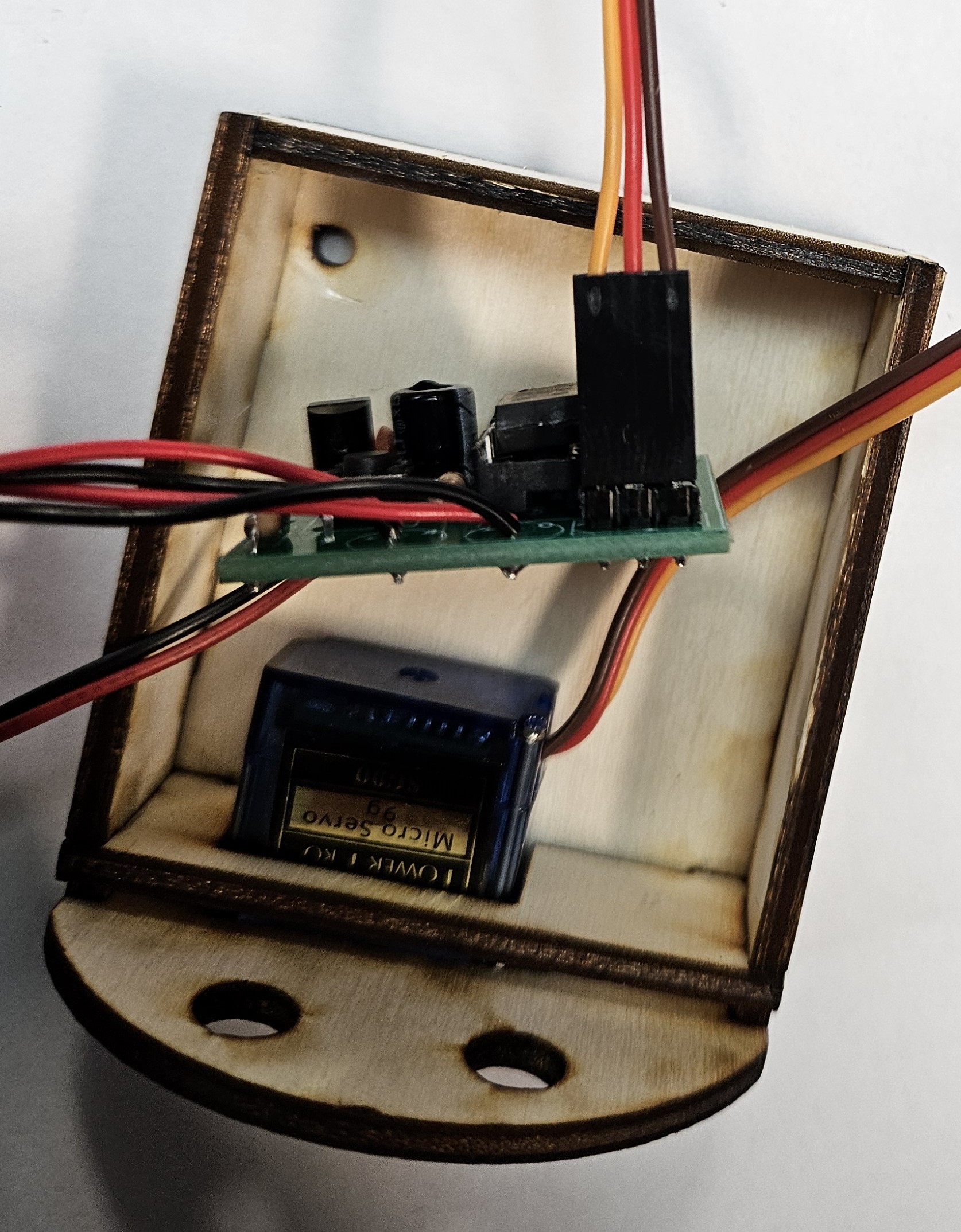
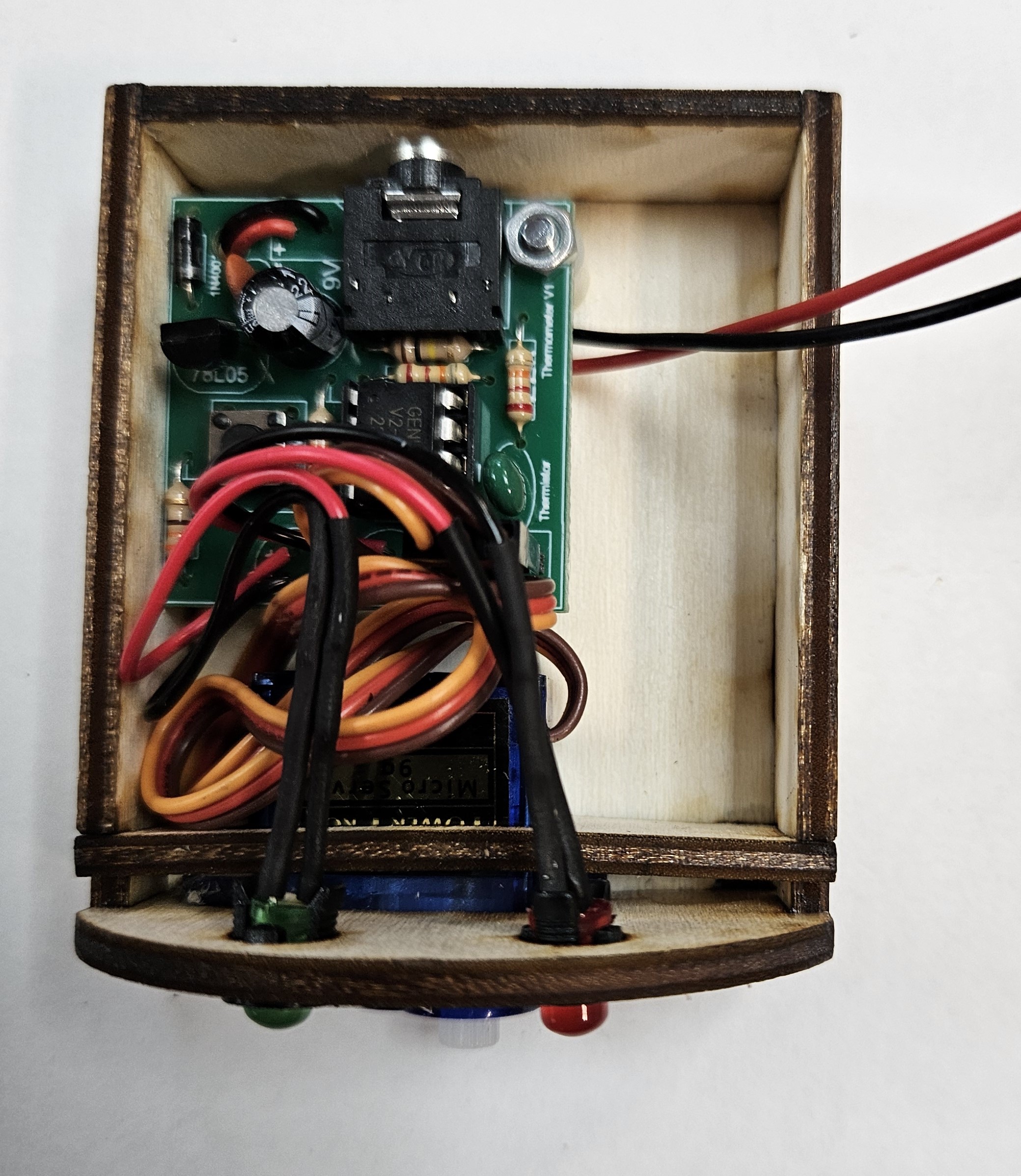
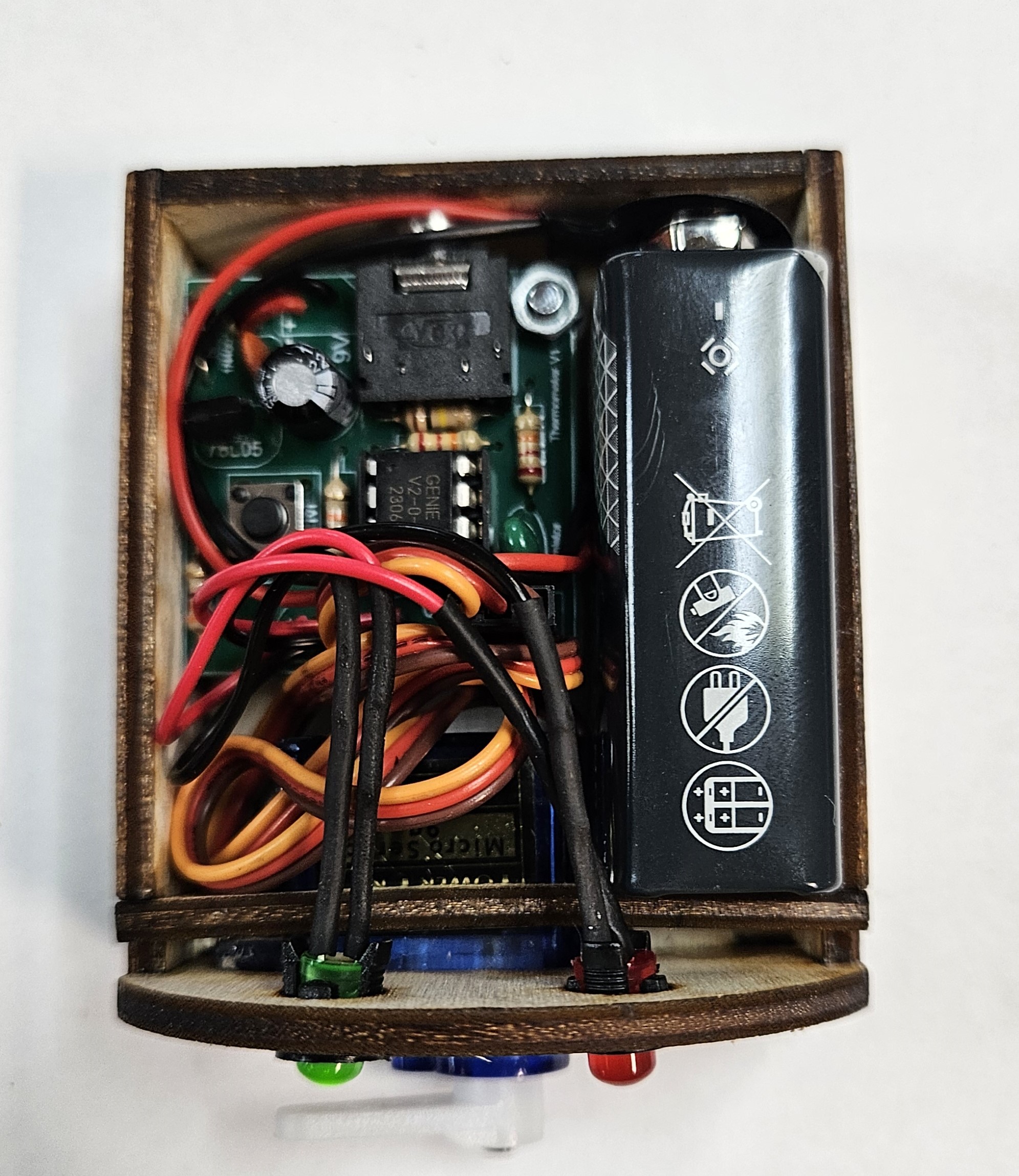
Note, the orange wire is the signal wire, the red wire is positive and the brown wire is negative. Make sure they are the correct way around (brown on the edge of the PCB)
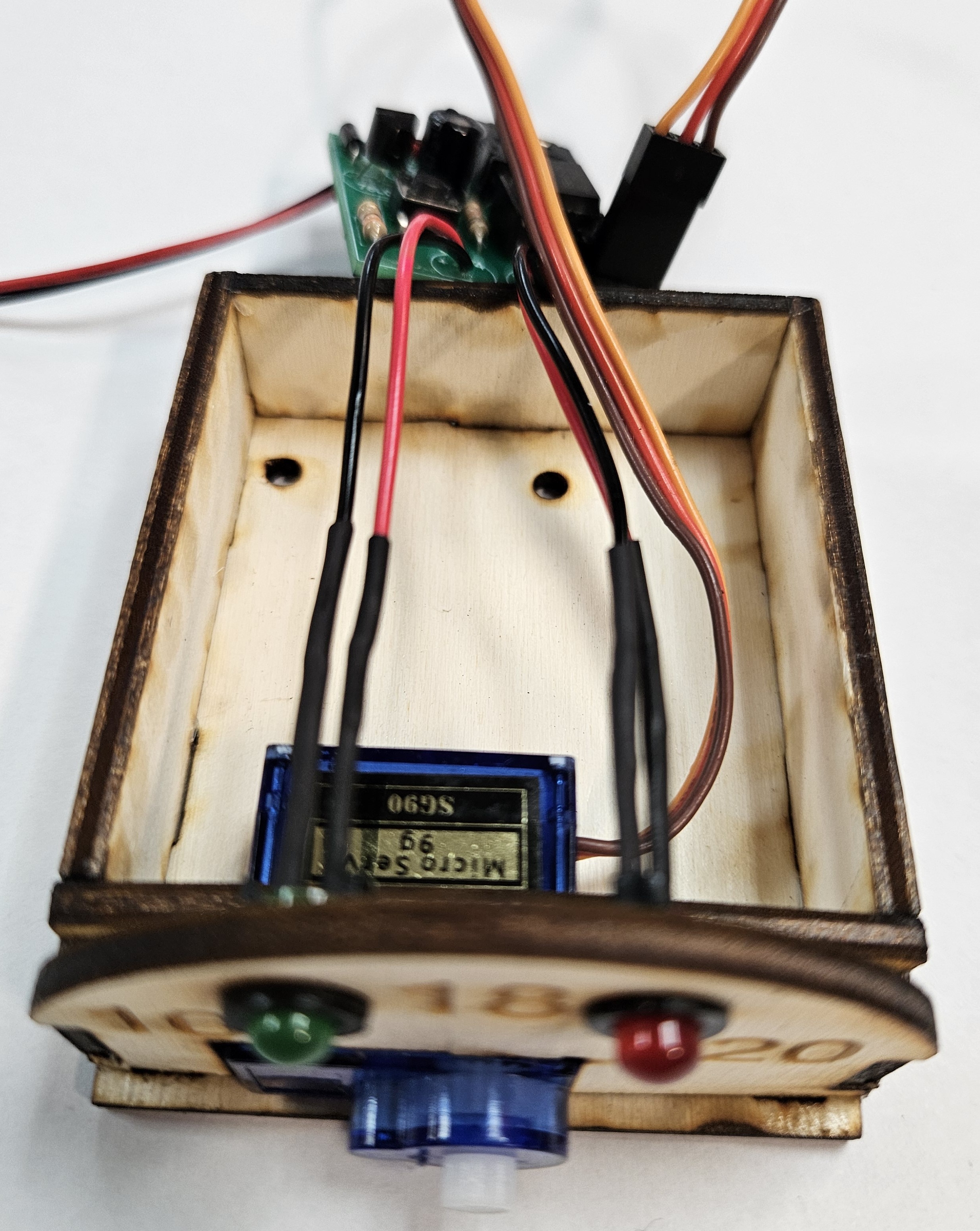
You can now place the LED clips in the housing and then connect the LEDs.
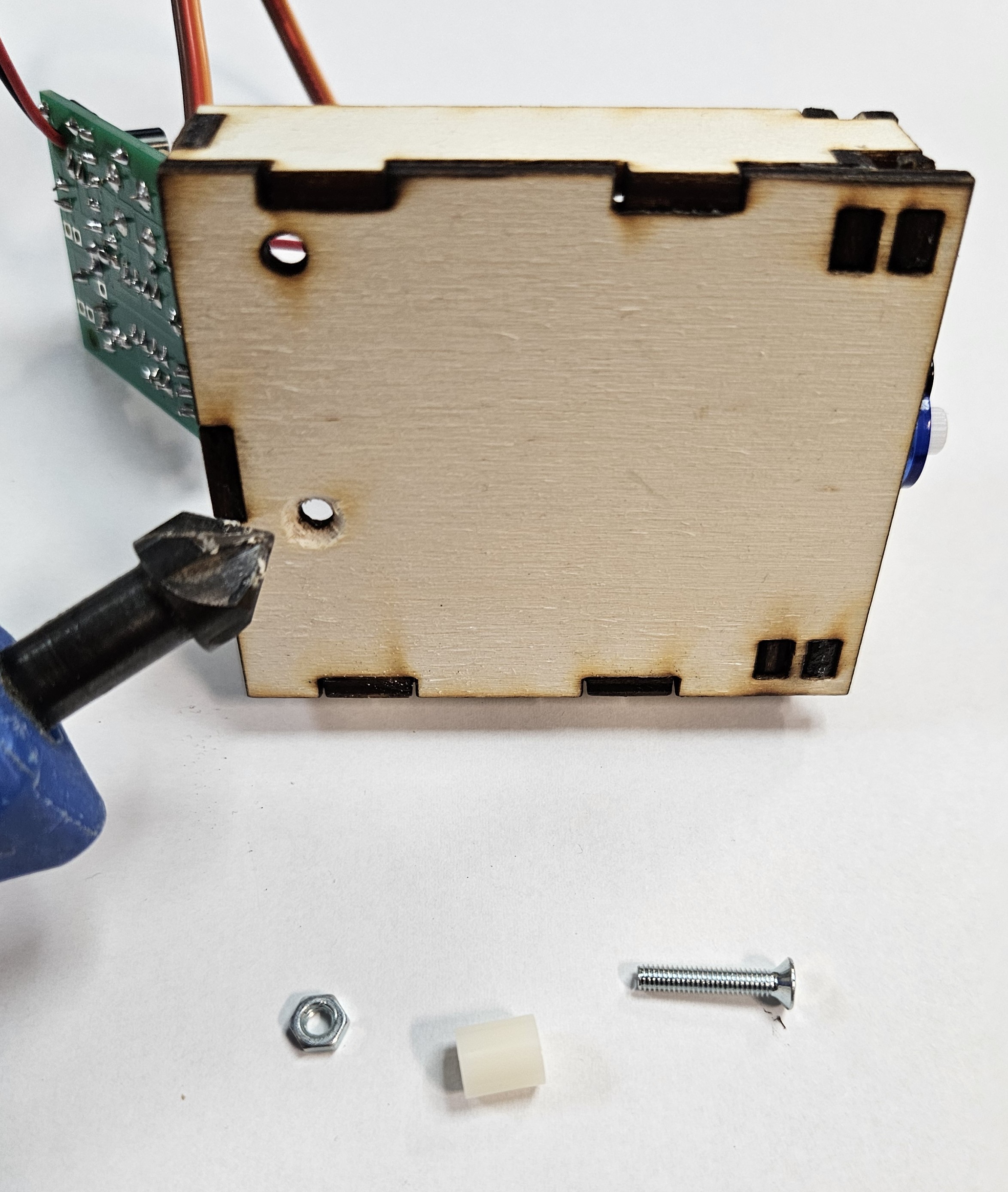
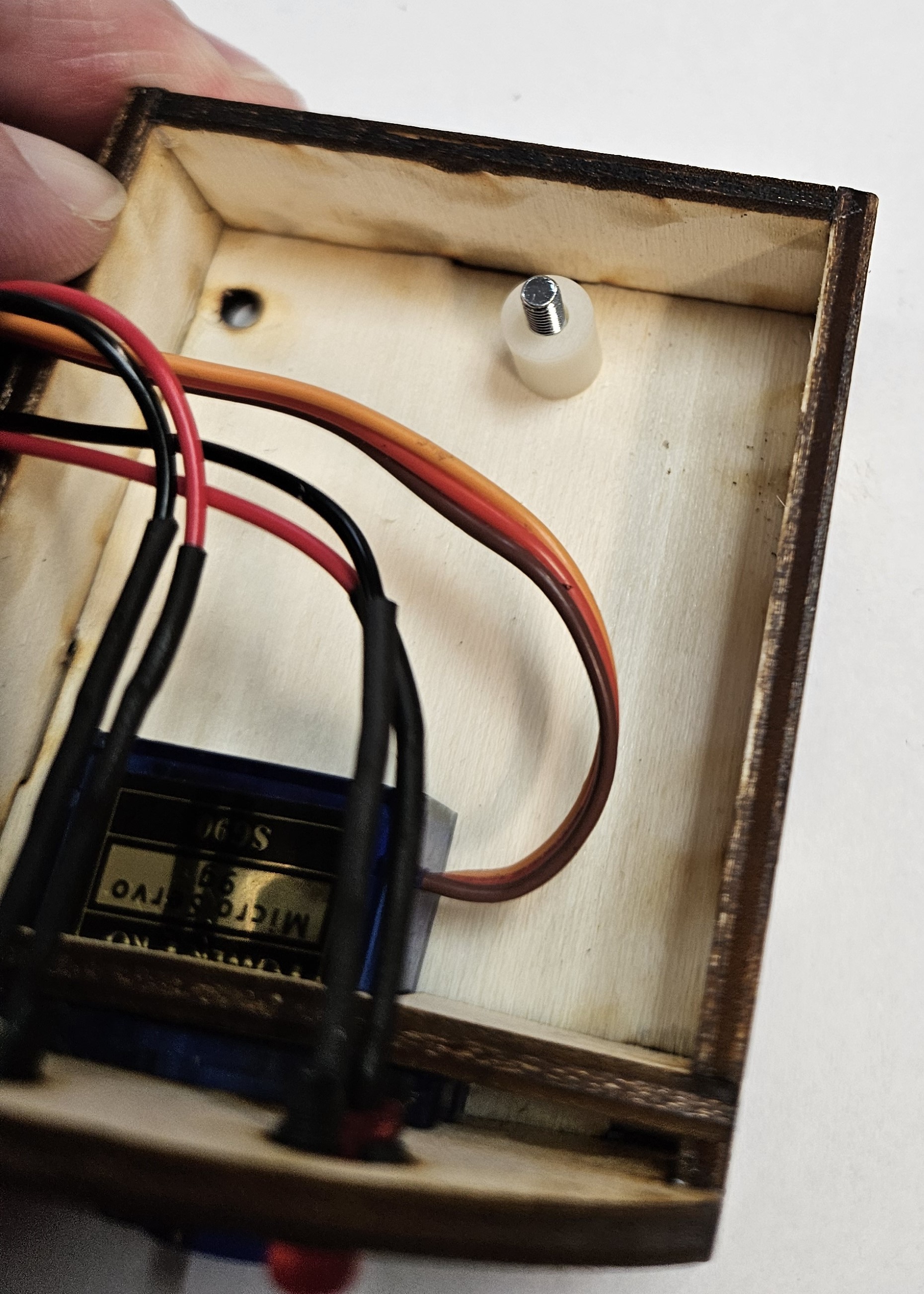
You will need to then countersink the hole on the bottom and place a screw through the housing with a spacer on the other side.
You can now place the PCB on the spacer and place the M3 nut on top. Then tightening it up with a screwdriver.
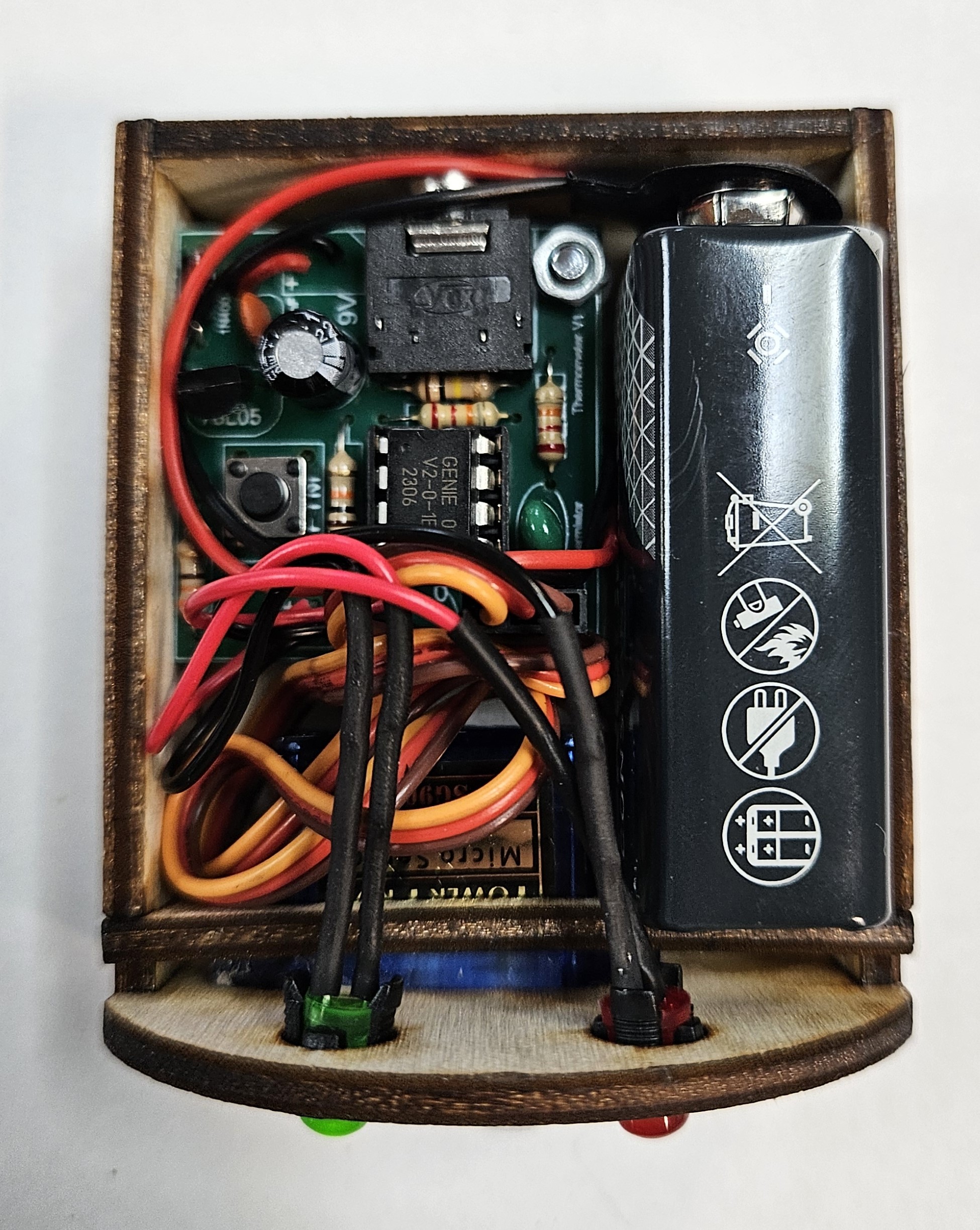
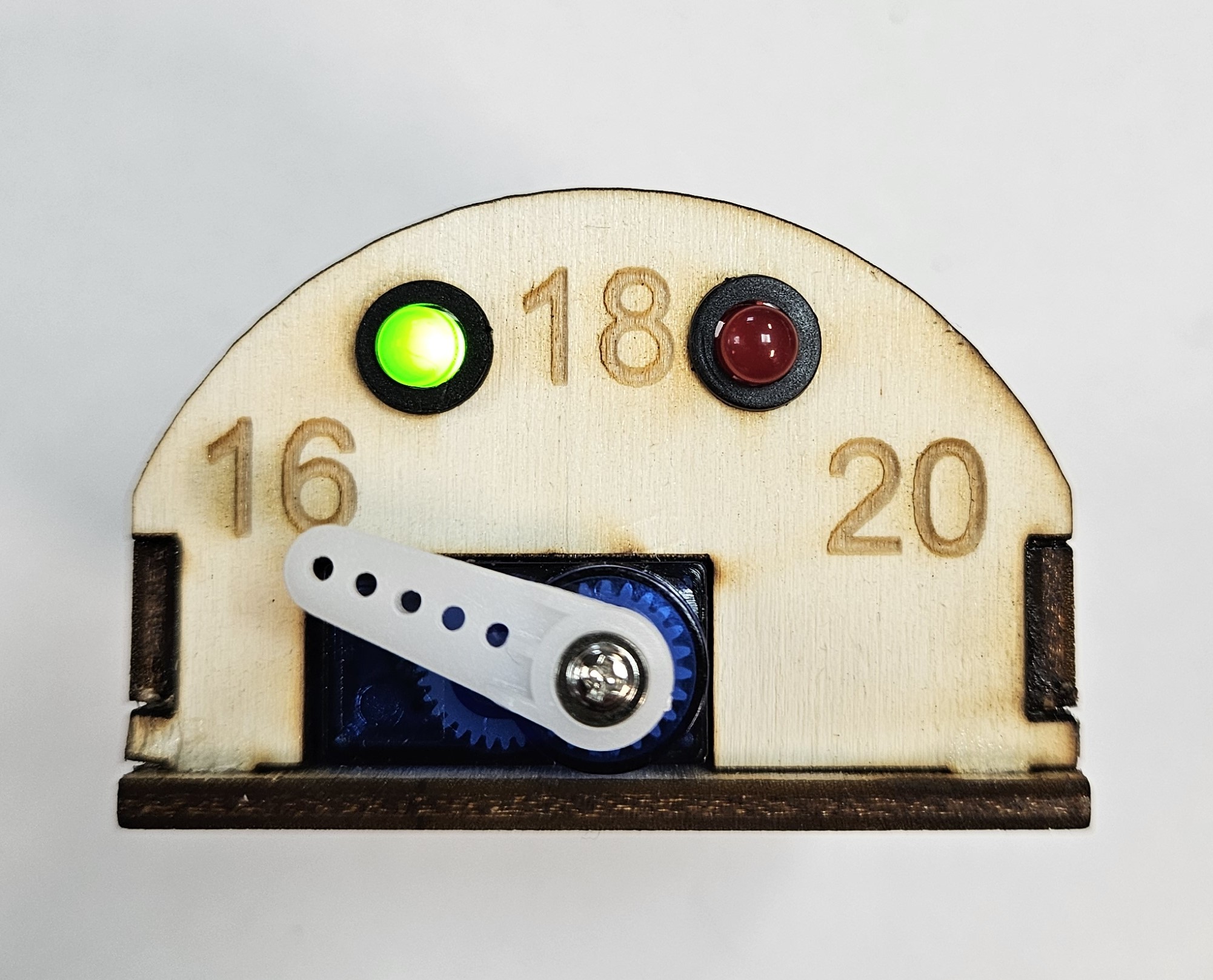
You can now place the battery in place and test the program. The servo horn is not yet connected as this will need to be running first to place it correctly.
With the battery in place, you will now need to press the PTM switch. This will do a servo sweep from full left to right. When it stops, you can place the servo horn on the motor pointing to 16 degrees. You can then add the screw found in the bag with the servo.
Badge It
Take pictures of your digital Thermometer for assessment.
The silver badge is progress ladder green - Produce a working model from parts supplied by a teacher, with limited assistance.
The gold badge is progress ladder blue - Produce challenging, high-quality, working products with very limited teacher assistance.
The platinum badge is progress ladder indigo - Independently produce fully working, high quality products.