Please follow the step-by-step instructions to solder the PCB together.
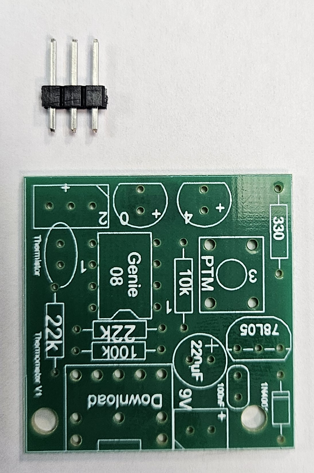
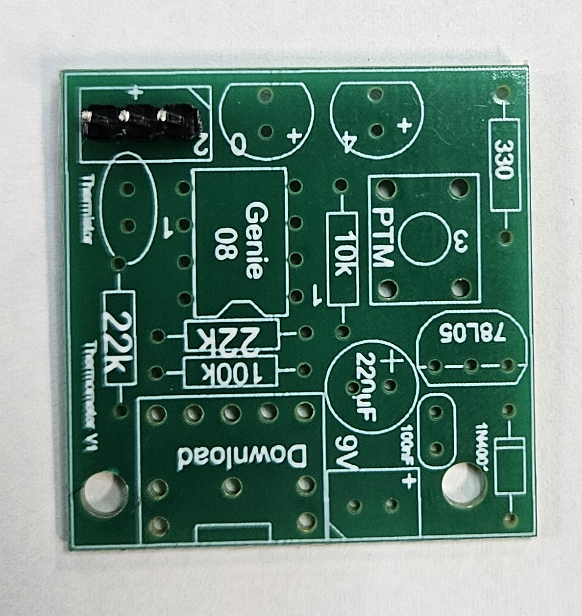
You will need to start with the SIL (single in line) header pins - 3 in line.
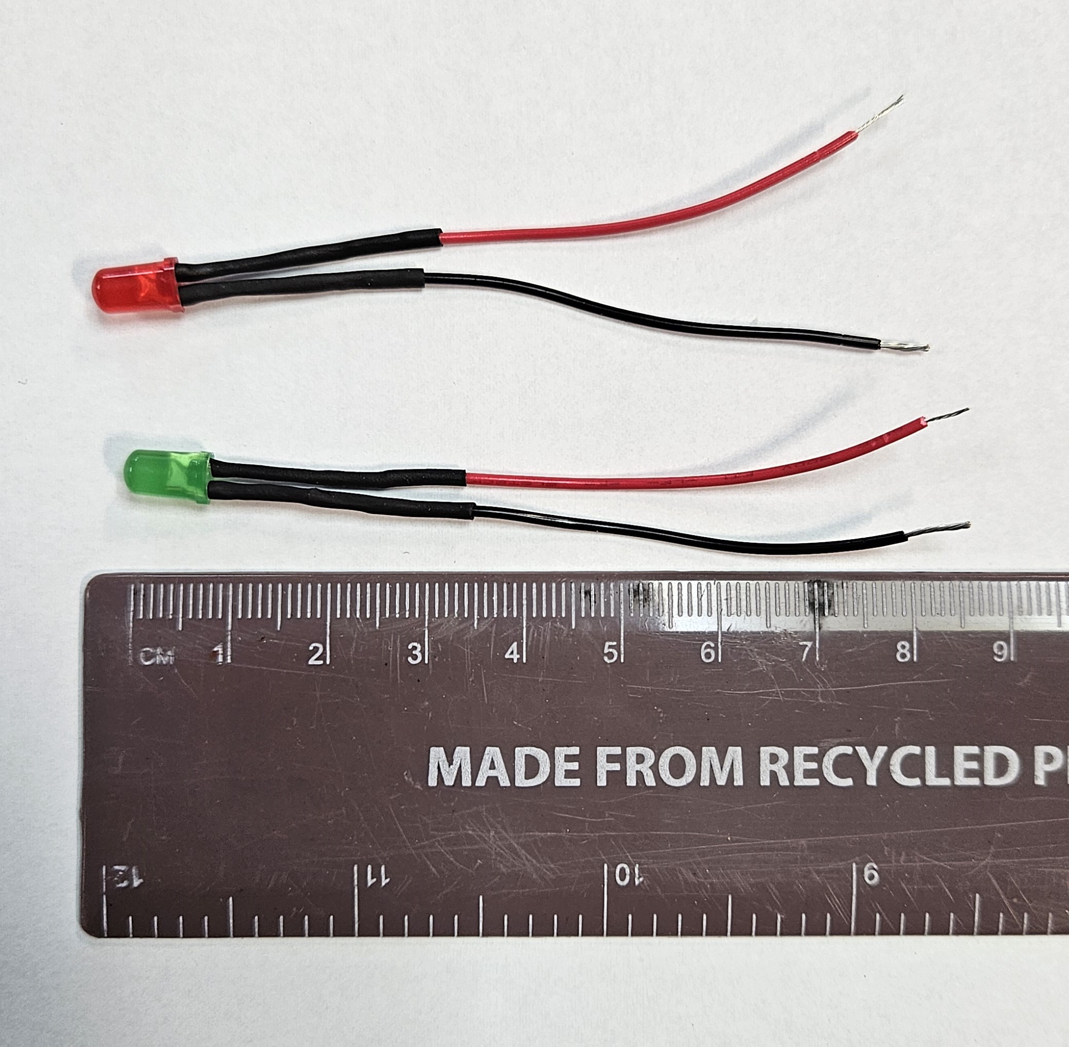
You will now need to solder 2 LEDs onto wires.
If you can not remember how to do this please go the the Year 7 Door Buzzer project to read the instructions of watch the tutorial videos.
The wires will need to be approximately 8cm (80mm) long.
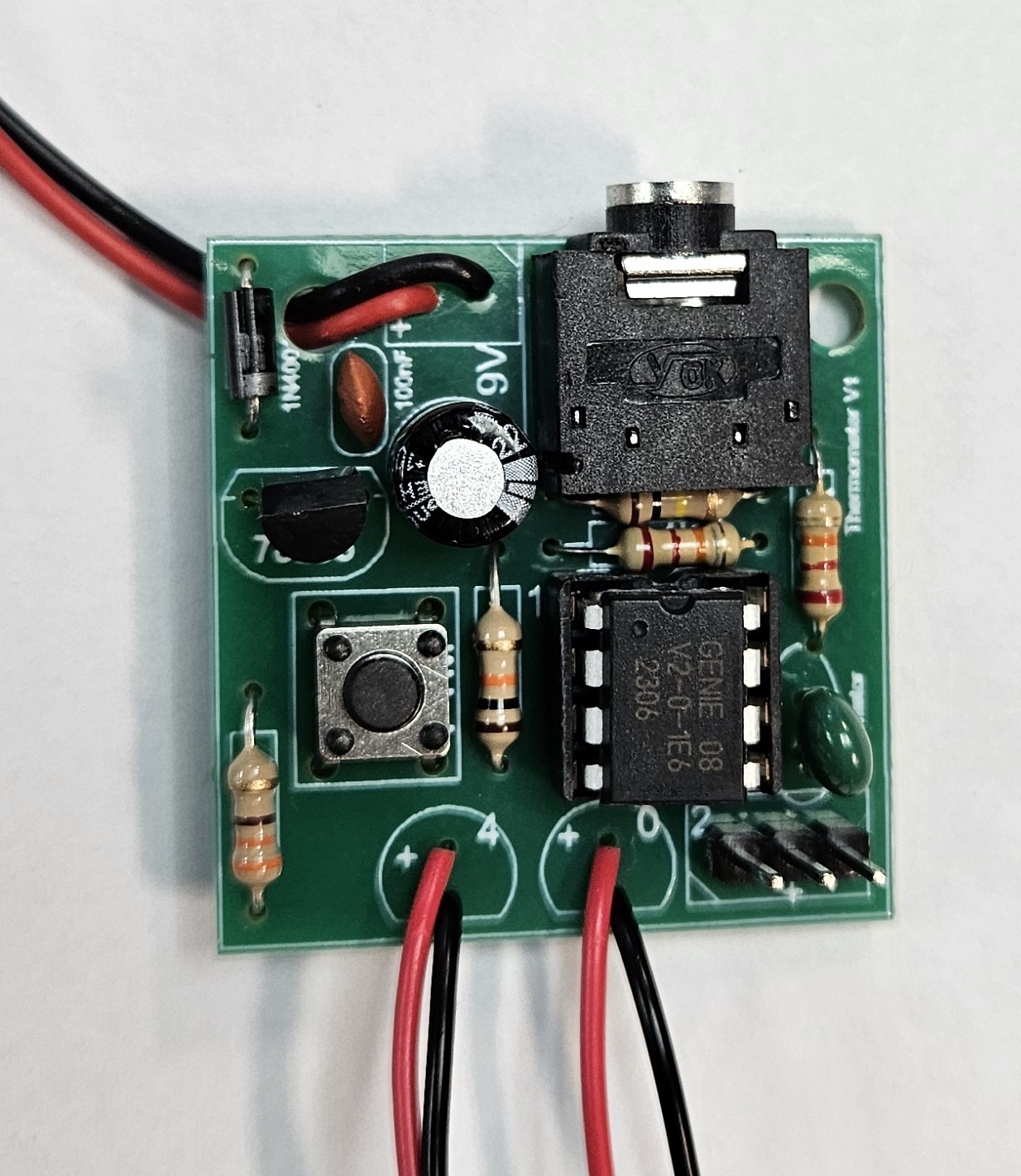
You can now solder the rest of the components to the PCB.
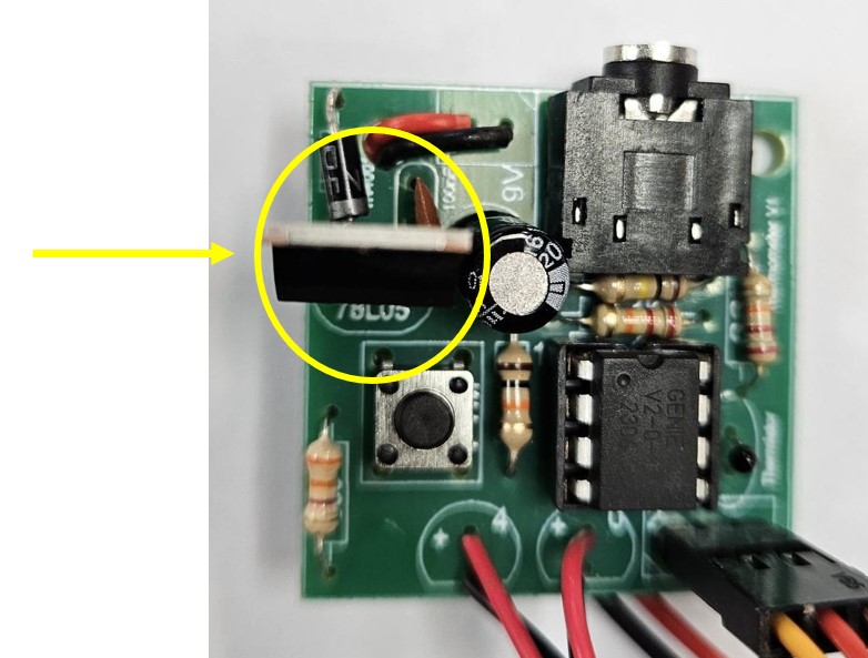
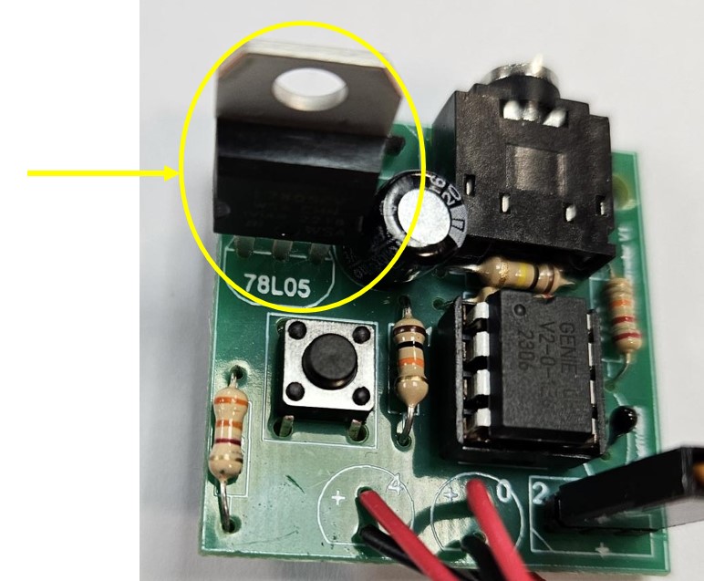
We need to change the 78L05 voltage regulator for a 7805 regulator. Below are images of the change.
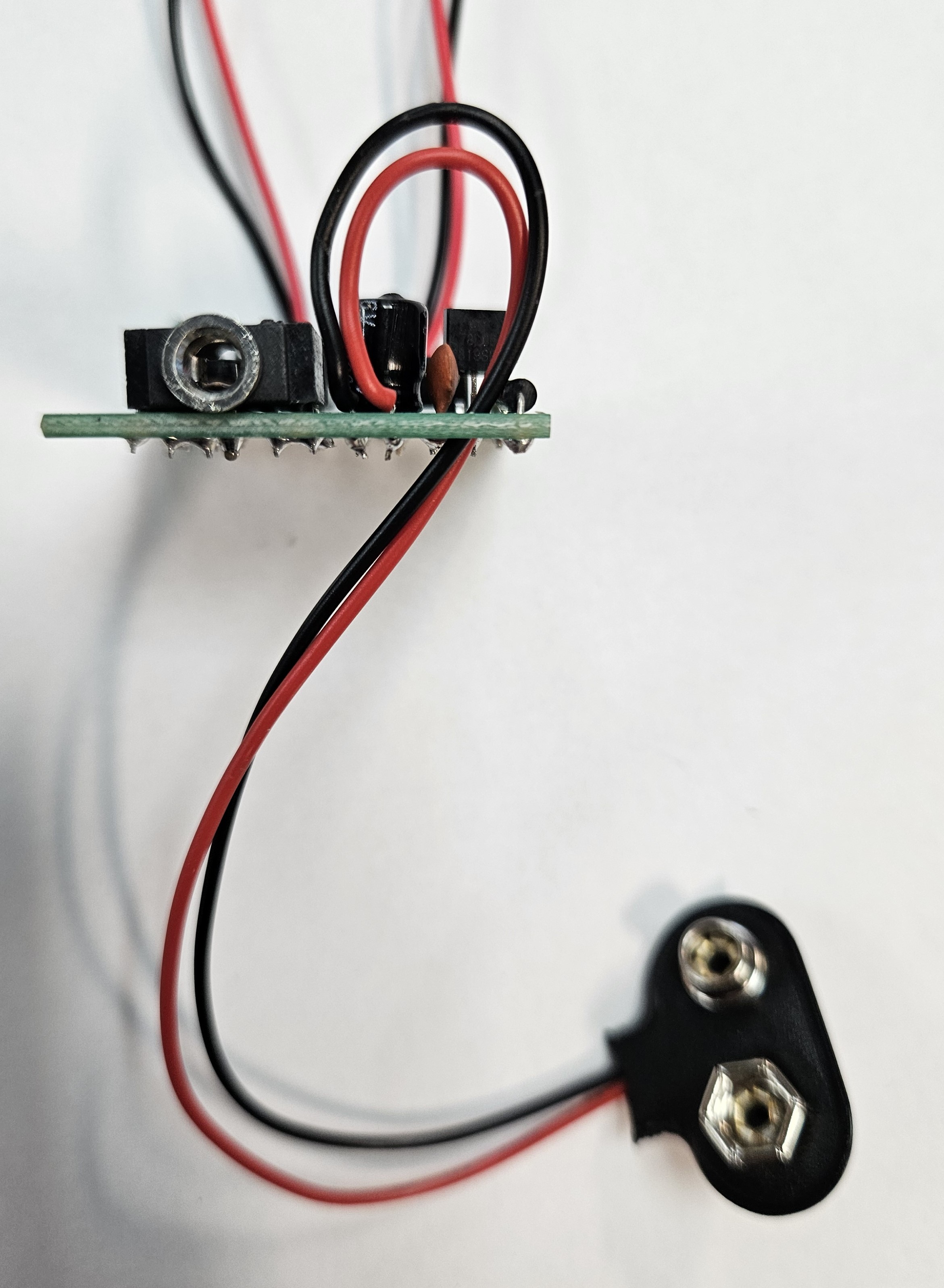
Don't forget to put the battery snap wires through the strain relief hole.
Once you have completed the soldering, you can plug in the Genie 08 microcontroller and download and test the program (make sure the Genie 08 is the correct way around).
Badge It
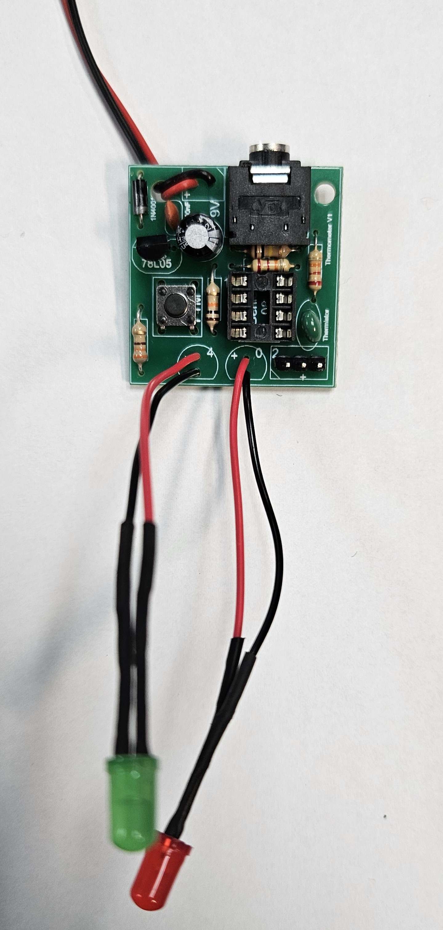
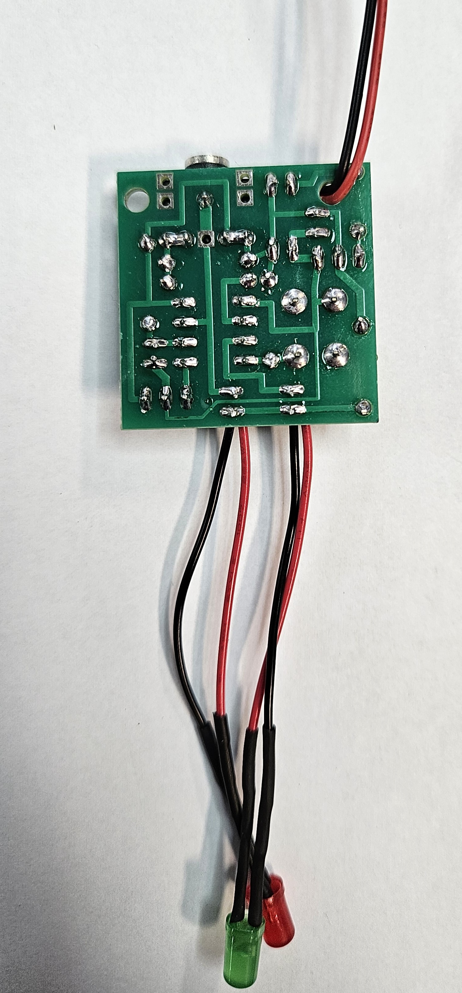
Photograph both sides of your board.
You will be awarded a silver, gold or platinum badge depending upon the quality of your soldering, flying leads and component placement.