Introduction.
Reminder of what PIC chips are. This is a very similar circuit to the PIC license.
Peripheral Interface Controllers are small silicon chips which can be programmed to perform useful tasks. In school, we tend to use Genie branded chips, like the 08 model you will use in this project. Others (e.g. PICAXE) are available. PIC chips allow you connect different inputs (e.g. switches) and outputs (e.g. LEDs, motors and speakers), and to control them using flowcharts. Chips such as these can be found everywhere in consumer electronic products, from toasters to cars.
While they might not look like much, there is more computational power in a single PIC chip used in school than there was in the space shuttle that went to the moon in the 60's!
Getting started with PIC circuit design.
Design time
- Open up the Circuit Wizard program you started in lesson 1.
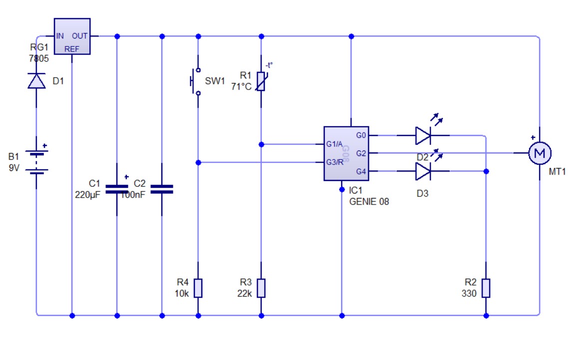
- We are now going to add the servo and complete the circuit below.
- The Genie 08 chip can be found in the "Microcontrollers" drop-down menu item.
- The battery can be found in the "Power Supplies" drop-down menu (right at the top). Change it to 9V.
- The voltage regulator (7805) is also found under Power supplies and is the last option.
- The LED can be found in the "Light Emitting Diodes" drop-down menu, be careful not to choose the "diode" option.
- The Thermistor can be found in the "Sensors" drop-down menu (right at the top).
- The Servo motor can be found in the "Electromechanical" drop-down menu (right at the bottom - 2nd to last).
- The capacitors can be found under capacitors - note that one is electrolytic and one is not. Change the values and the units if necessary.
Badge It Silver
Silver Badge
- Before uploading your work, click on the 'Standard' tab on the left side. This is the view you need to upload.
- Take a screenshot of the final circuit diagram for the silver badge and upload it to bournetolearn.com. 9th badge from the top.
Programming
- You will now need to write a code to get the servo to point to different temperatures as needed.
- You will also need to include a red and a green LED to turn on when it it cold or hot accordingly.
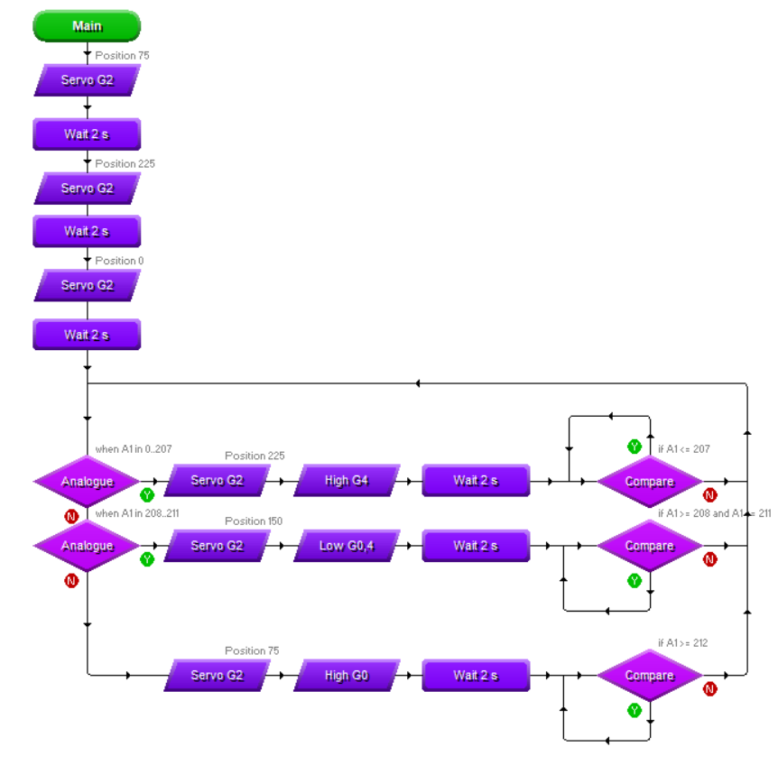
- Lets start with the servo code. Remember how we added the thermistor and servo code from the previous lessons.
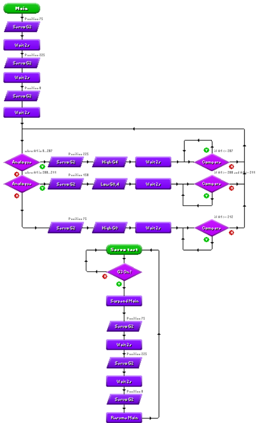
- The program will start by doing a 'servo sweep' to make sure it works and has the full range of motion (this could be a subroutine to simplify the program later).
- It will then need to monitor the thermistor/analogue value for the different temperatures.
- One big issue with servo motors is that you do not want the servo instruction in a loop, this will cause the motor to constantly jump.
- To fix this, we add the compare decision after the motor has moved and set it to stay in the compare loop until the analogue value changes to the next setting. This will stop the servo from constantly trying to move to the same position.
- Now the temperature monitoring setup is now complete, we want to add a program the can test the servo when you press the PTM switch.
- To do this, we will add another start to the same program, which you will need to rename. You can call it Sweep test (or anything you like)
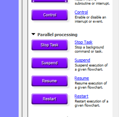
- You will also need to use the 'Suspend' instruction which can be found under 'Parallel processing' towards the bottom of the drop down list.
- The program will start an monitor the digital input (PTM switch).
- If it is pressed, you need to suspend the Main program and then repeat the servo sweep test in the servo program.
- Hint: You could simplify the program by putting the sweep test in a subroutine.
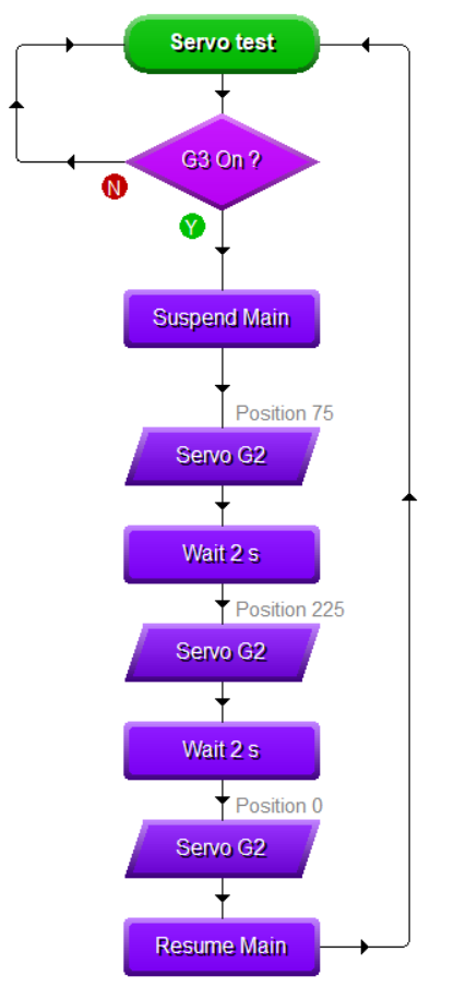
- Here is what the finished code could look like.
Badge It - Gold
- Before uploading your work, click on the 'Standard' tab on the left side. This is the view you need to upload.
- Take a screenshot of the program for the gold badge and upload it to bournetolearn.com 10th badge down.
Badge It - Platinum
- All of your thermistors will give a slightly different number for the analogue reading for the current temperature so we need to calibrate them.
- Connect your PCB with a cable and battery to your PCB.
- Click on the program tab on the right hand side.
- Select the option 'Calibrate sensor'. You should now see the analogue reading your thermistor is on.
- Ask your teacher what is the current temperature in the room.
- If it is on the cool side i.e. 16 or below use this as the second number in the first decision diamond i.e. 0-40
- If it on the hot side i.e. 21 or above use this as the second number in the second decision diamond. 41- 44. Then make the first number three below.
- Once you have added the current number adjust all the numbers to match it. For exampl: 0-40/ 41- 44 both diamonds on the left and the right and the third decision on the right above 45.
- Take a screenshot of the final program for the platinum badge and upload it to bournetolearn.com 11th badge down.