
How do servo motors work?
Learn It
- A servomechanism (servo) can refer to quite a few different machines that have been around longer than most may realise. Essentially, a servo is any motor-driven system with a feedback element built in. Servos are found everywhere from heavy machinery, to power steering in vehicles, to robotics and a wide variety of electronics.
- There are 2 types of servo motors:
- A standard hobby or “closed-loop" servo will have a movement range of 90 or 180 degrees. Some will be slightly greater or lesser than the specified range, so check the specifications of the motor you wish to use before implementing it in your project. Standard servos provide feedback for the controller to monitor its position on the movement arc over the control signal wire. This allows you to move the servo to precise locations with the right pulse length from your controller.
- Continuous rotation or “open-loop" servos do not work like the standard servo. The control signal only controls direction and speed, not position. These enable you to easily control how fast the drive shaft is moving and which direction it's going, but there's no feedback for position control, so they are not recommended for applications that require moving between specific points on the rotation arc.
- For this project, we will be using the standard hobby servo.
Learn It
- The microcontroller uses Pulse-Width Modulation (PWM) to drive the servo into the correct position. You have learned about PWM in the 555 fan project.
- When connecting a servo, you need to ensure the pin is capable of PWM.
- All 3 outputs of the Genie 08 can be used for PWM, although it is best to avoid G0 as it is also status and will pulse when connected to the computer, causing errors.
Try It
- Let's build a simple circuit to try and get a GENIE chip to drive a servo motor
- Use the Circuit Wizard file you created from lesson 1 to build/add on to for the circuit shown below
- When opening circuit wizard, you need to choose the 'Circuit with GENIE Flowchart' option.
- You will find the Servo is under 'electromechanical' in the drop down menu (towards the bottom).
- You will find the Genie 08 under 'microcontrollers' in the drop down menu.
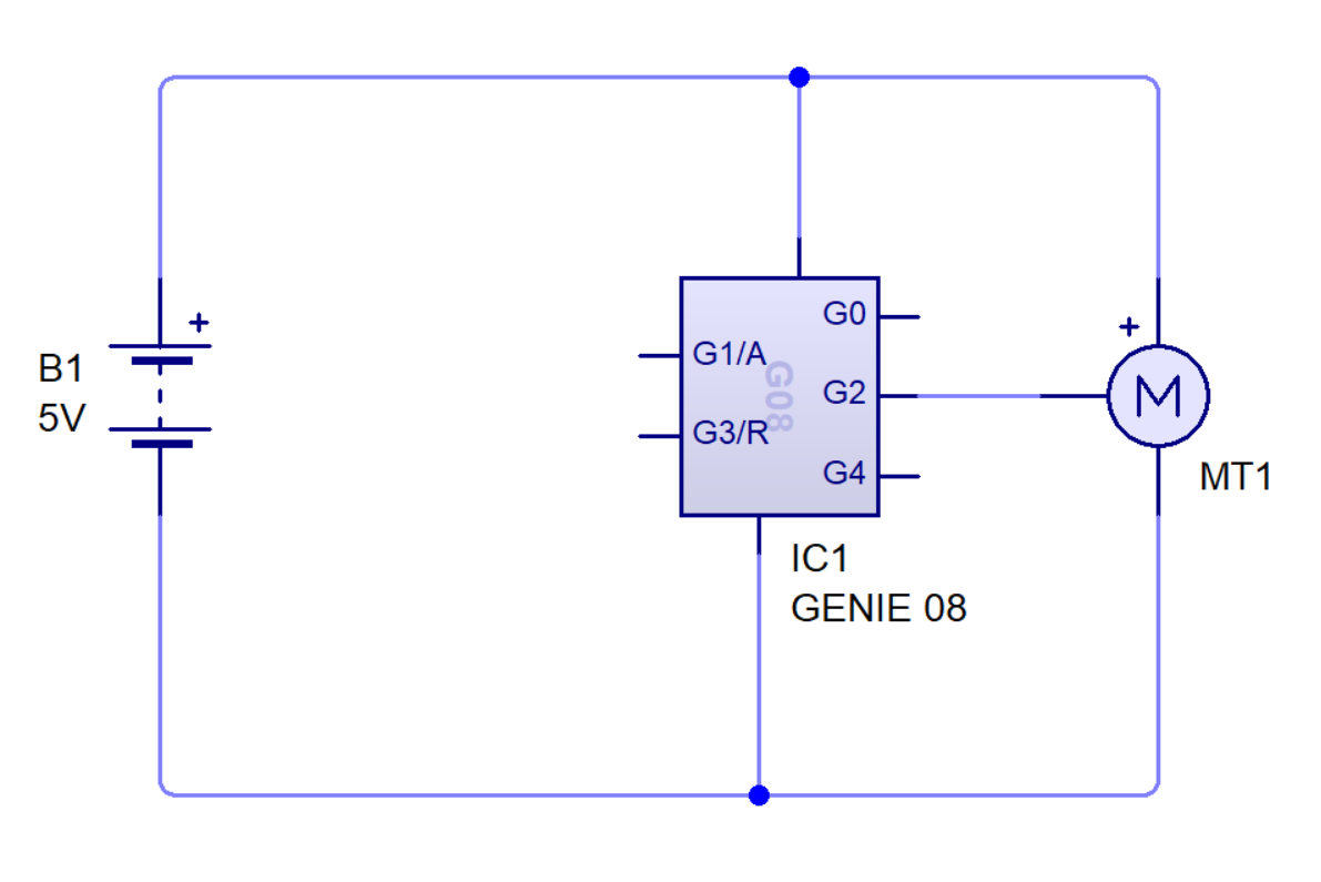
- We will now need to write a code to get the servo motor to turn.
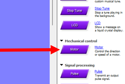
- Add the motor block to your flowchart.
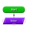
- Now you need to add the setting to the motor block.
- Double click on the block and then select 'servo'
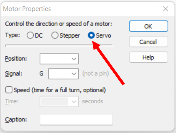
- You will now need to select the position you want the motor to turn to.
- Note, the range is from 75 to 225 (0 is not a position - this can be confusing as the usual analogue range is 0-255)
- 75 = 0 degrees
- 225 = 180 degrees
- You will start with position 75.
- You will also need to select the output you have connected the servo to, in this case it is G2 (remember, G0 is to be avoided as it is also status)
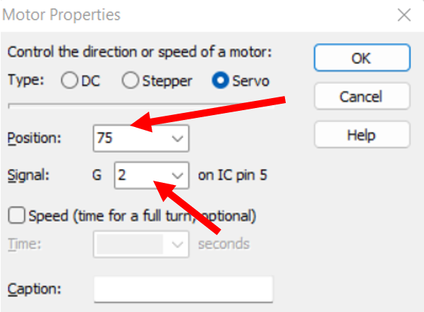
- After this is setup, you then need to add a wait and then repeat this code to move it to position 225 (180 degrees).
- NOTE: you can also set the speed at which the motor takes to move the the set position when you are in the motor block settings.

- You can now go back to the circuit diagram and run the program.

Badge It - Silver
- Design the circuit above and write a program to get the servo motor to turn 90 degrees instead of 180 degrees.
- Upload images of both the circuit and flowchart for the badge.
2 Setting up visual outputs
Try It
- In the lesson before, you learned how to add the thermistor to the input.
- Add a thermistor to the circuit above (don't forget the voltage divider resistor).
- We're going to need a couple of LEDs (one red and one green) attached to the digital outputs of the GENIE chip.
- Don't forget that LEDs are sensitive to large currents can can 'pop' if the current is too high. A couple of 330 Ω resistors should be sufficient to protect them.
- Hint: You have added LEDs before in the PIC license project. Click on this link to revisit the topic.
Badge It - Gold
- Write a program (flowchart) to get the servo motor to turn when the temperature goes above 25 degrees Celsius (temperature).
Try It
- We're going to need a couple of LEDs (one red and one green) attached to the digital outputs of the GENIE chip.
- Don't forget that LEDs are sensitive to large currents can can 'pop' if the current is too high. A couple of 330 Ω resistors should be sufficient to protect them
Badge It - Platinum
- Add to your previous flowchart. When the temperature is below 25 degrees Celsius, the green LED is on and when it gets to 26 degrees and above the red LED turns on (red on and green off and vice versa)