Quick Makes
Drawdio
Learn It
- We can create different tones by creating different frequencies.
- In the previous project(The Egg Timer) you learned about 555 timer circuits.
- These circuits can produce pulses which change the frequency.
Try It
- Look at the video below to see how the frequency changes when you adjust the resistance.
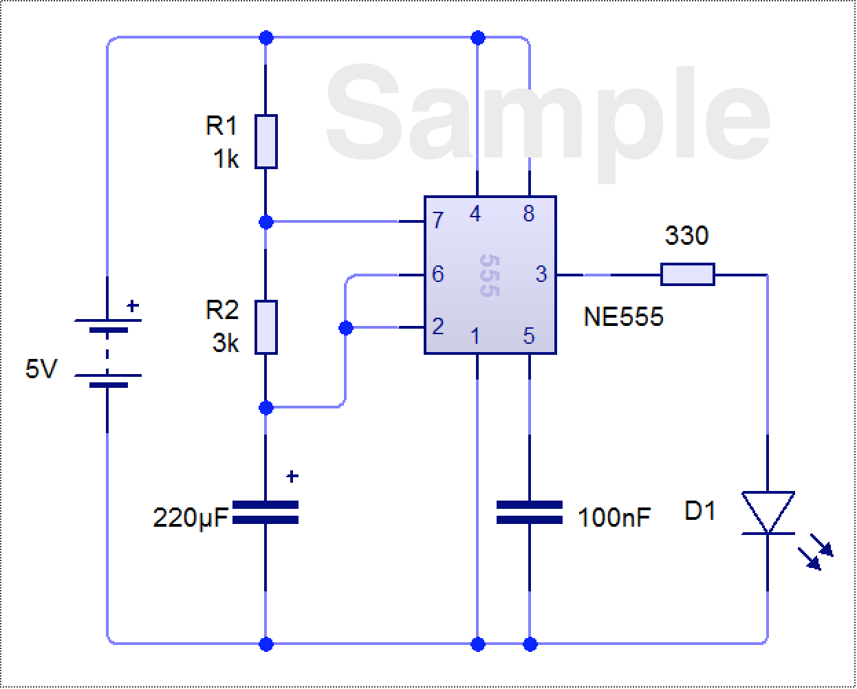
- Try building the circuit above using circuit wizard.
- Change the values of VR1 and see how it affects the speed at which the LED flashes.
Build It
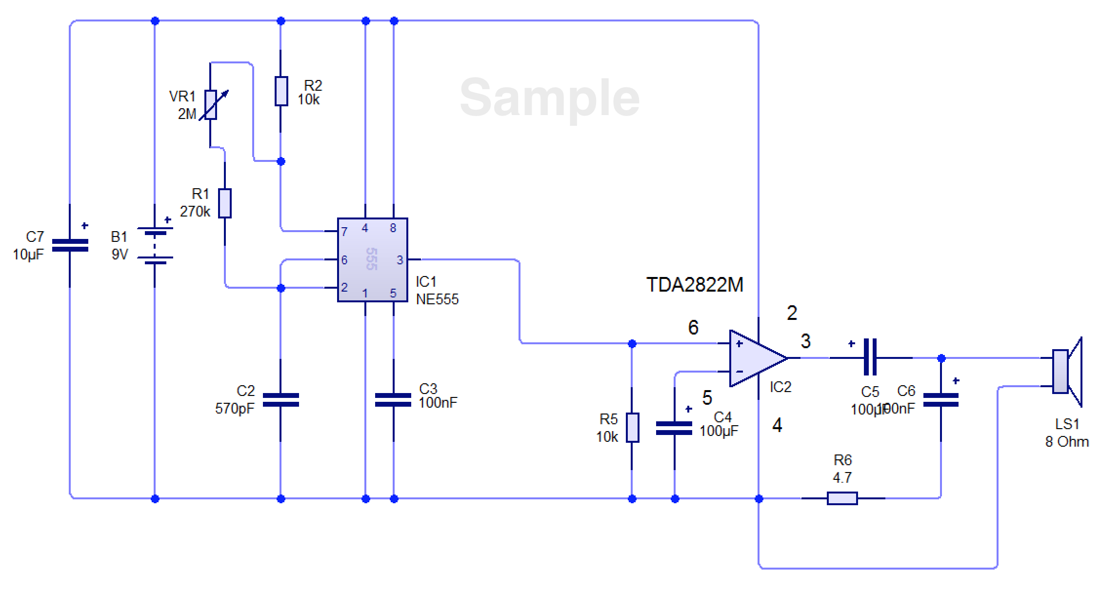
- Below is the full circuit diagram. if you have time, you can try design one yourself.
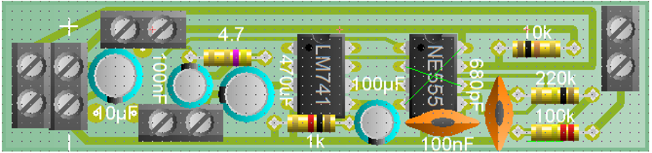
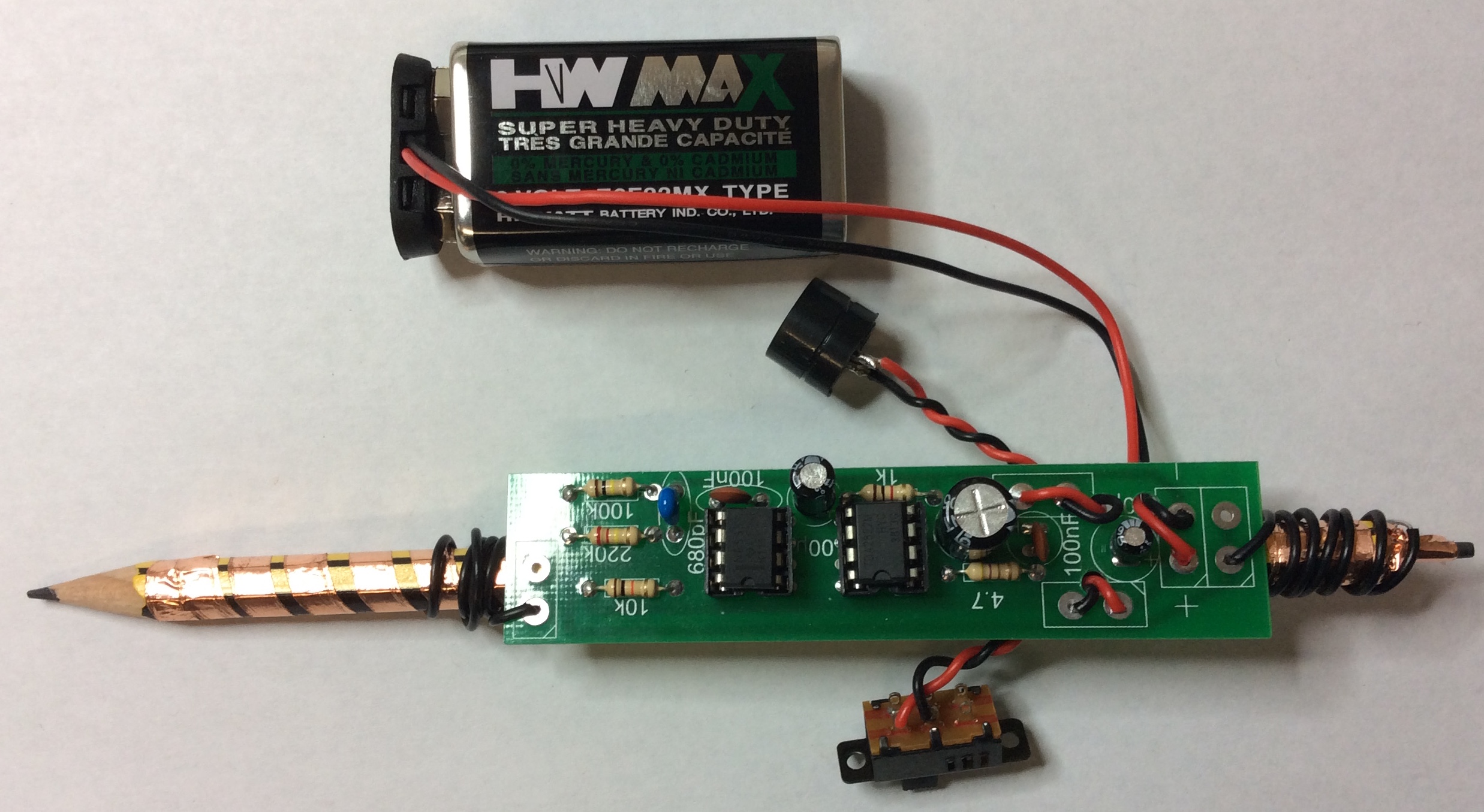
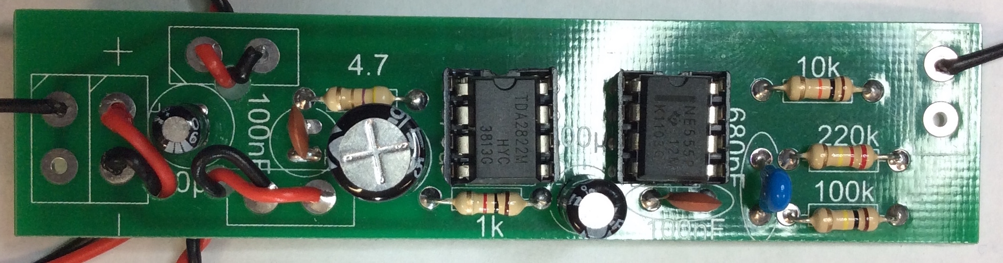
- Your circuit board will look like this. Please note, the LM741 is actually a TDA2822M
- This will need to be replaced.
- As usual, always start building with the smallest components first (the resistors).
- Once you have finished your PCB, it should look like this.
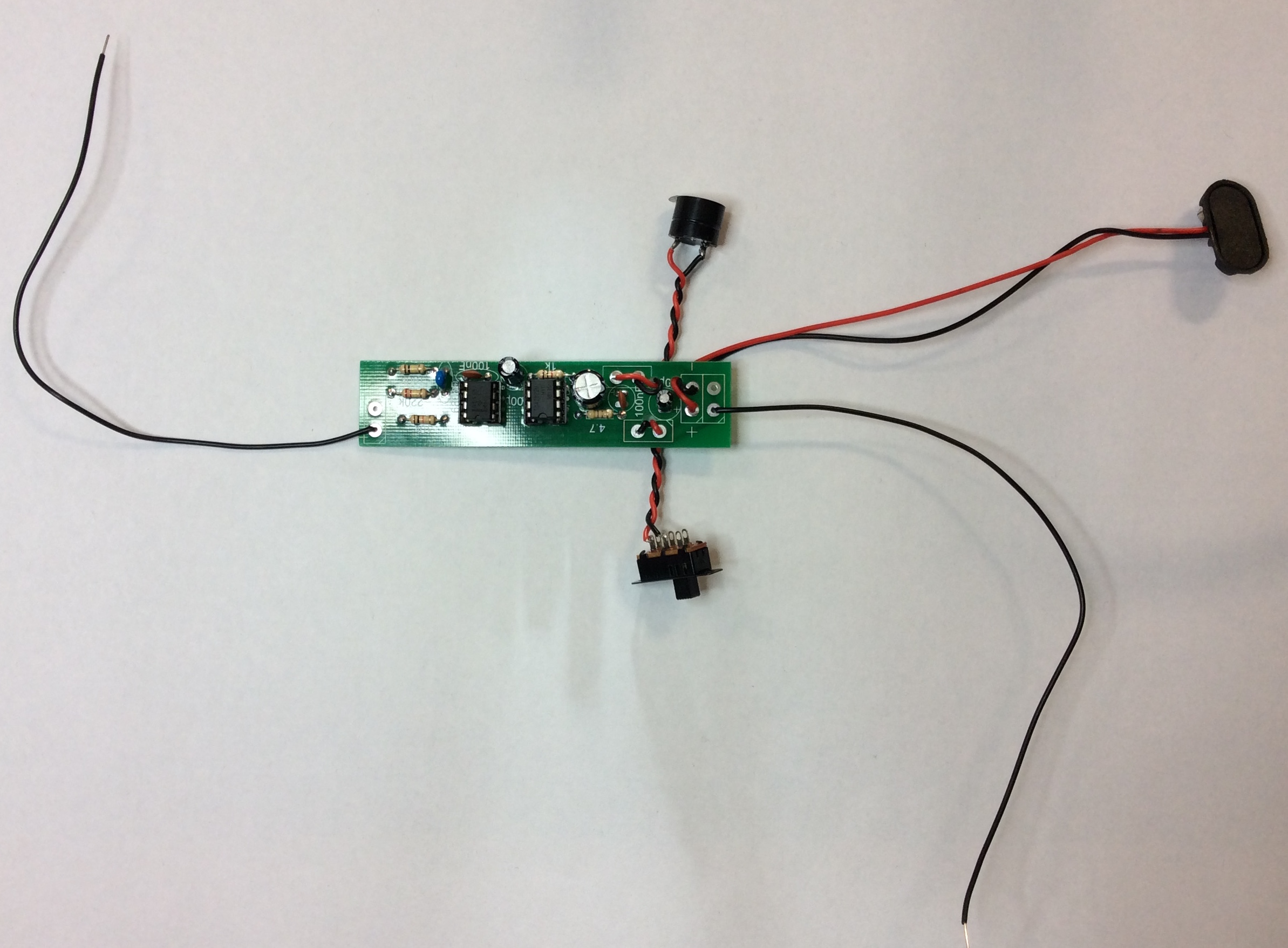
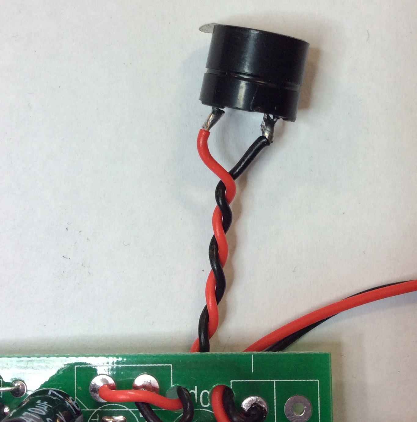
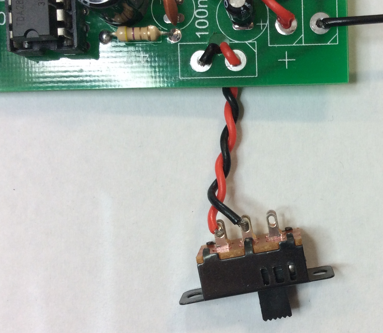
- Below are some close-up pictures of how to connect the buzzer and switch.
Build It
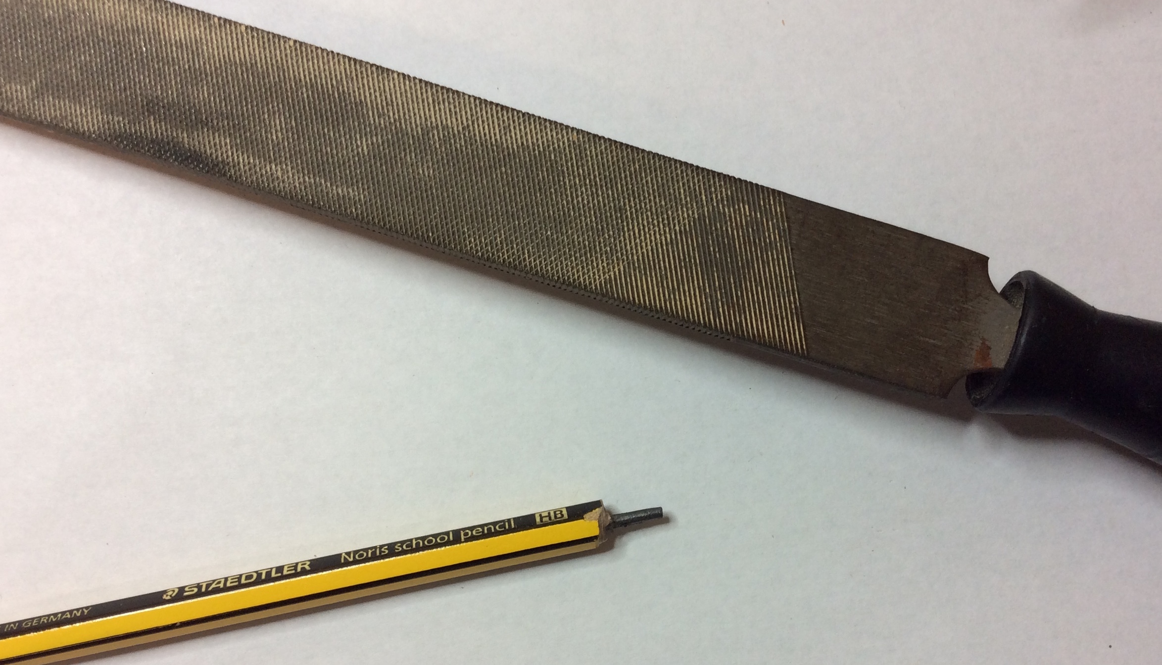
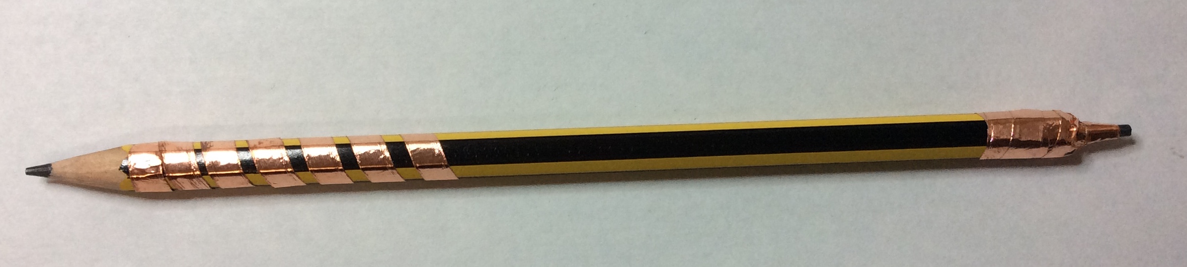
- Now you need to attach your Drawdio to a pencil.
- First file down the end of the pencil.
- Be very very gentle, or you will break the pencil.
- Now attach the copper tape to the top and bottom.
- You can now attach the board and solder the wires to pencil and neaten up the board.
Badge It
Silver
- Paste a screenshot of your 555 timer circuit you designed and paste it into the word document (Or upload the picture directly).
- Explain what happens to the frquency when you change the resistance value.
- Explain how the change in frequency will change the pitch of the buzzer.
Gold
- Upload photos of the front and back of your project.
- Your solder joints are good, some dry joints or excess solder.
- You component placement is good, a few of the components are off the board and not aligned correctly.
Platinum
- Upload pictures of your completed project here, if you have completed the project to a very high standard.
- No dry joints.
- No excess solder.
- Components legs have been trimmed well.
- The components have been placed on the board neatly.