The Drawer Alarm
1 Designing the PCB
Learn It
- Although the circuit you've designed should be fine, we need to make a few changes before we design a PCB
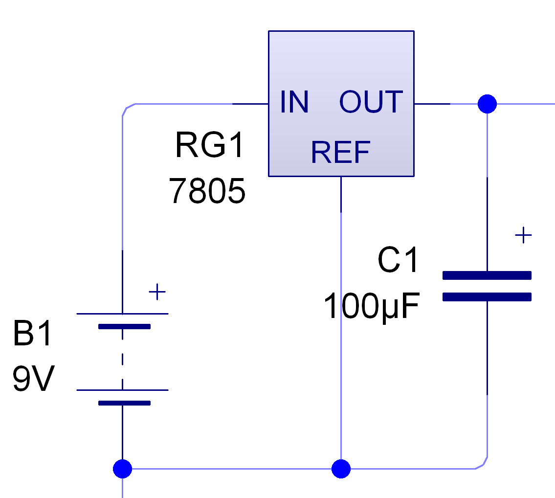
- Firstly we want to use a 9V supply (as they're cheaper), so we'll need a voltage regulator.
- Modify your circuit so you use the setup below to provide power.
- Check with your teacher that your circuit is correct before proceeding.
Try It
- You're now going to design your own PCB.
- Initially you just need to follow this guide.
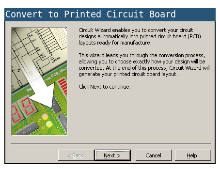
- Click on this button to begin the PCB Wizard, you will find it at the top of the workspace.
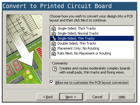
- Choose
Single Sided/Thin Tracks and check the box "Allow me customise the PCB layout conversion" at the bottom.
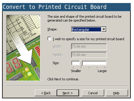
- The default size of the board will be fine
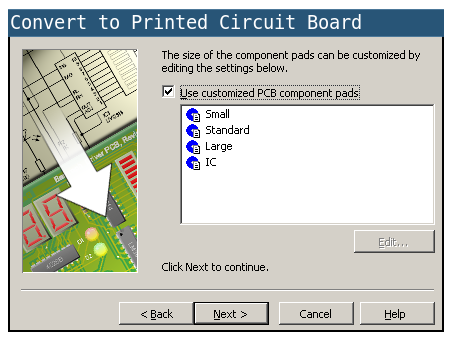
- As will the default components
- And we need to use small pads
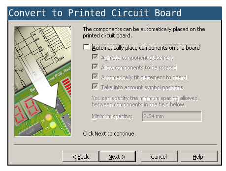
- Lastly uncheck the box, so that we can place components ourselves.
- Click convert and you should have something that looks a little like this.
Badge It
- It's now up to you to try and create the PCB.
- You'll be awarded your badge depending on the size and neatness of your finished design.
- A silver badge will be awarded if you create a viable PCB of any size, without using jump wires.
- A gold badge will be awarded if you create a viable PCB no larger than 100mm by 100mm, without using jump wires.
- A platinum badge will be awarded if you create a viable PCB no larger than 50mm by 50mm, without using jump wires.