Design Project
1 Circuit Design
Learn It
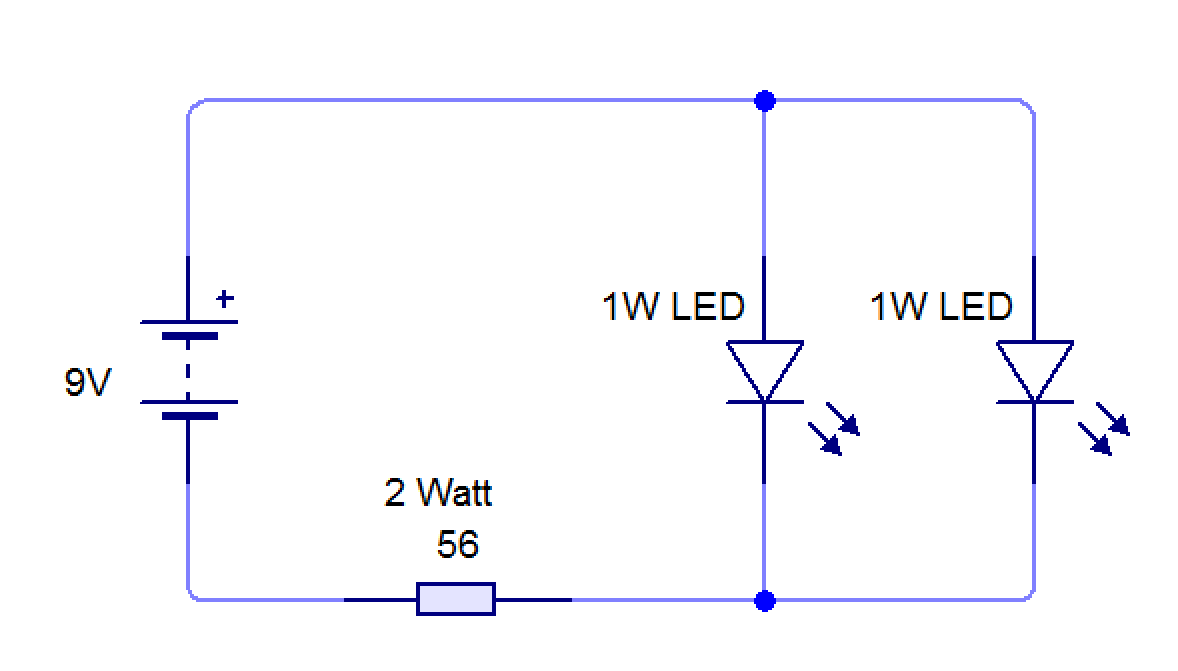
- The LEDs you're going to use are very bright, 1W models.
- They'll work with a good-quality 9V battery, but because LEDs have very low internal resistance, if connected directly to the battery they'll draw too much current, quickly overheat and burn out.
- To reduce the current flow and divide the voltage, we'll use a 56 Ohm, high power(2W) resistor connected in series with the LEDs, this will stop this from happening.
- You're going to need to design a compact Stripboard circuit to take all the component parts. We use DIYlc for stripboard design in School.
- Resource: You can load DIYlc from the open drive in School, in the G:\Design Engineering\Student Home software\DIYlc\ folder. Double-click the 'diylc.exe' file to start.
- Resource: At home, DIYlc is available for download here.
Try It
- Open DIYlc application, this is in the open drive: Design Engineering/Student home software/DIYLc - Double click on the application (.exe file)
- Note:
- The board is in the 'boards' option on the left (use the veroboard option)
- The resistors are in the 'passive' option on the left - you do not need to change the value of the resistor.
- The wires are in the 'connectivity' option on the left - Choose the 'hookup wire' option. You can change the colour by right-clicking on the wire and clicking on 'edit selection'.
- The LEDs are in the 'semiconductors' option on the left
- The holes are in the 'connectivity' option on the left (called eyelets) - You can change the size by right-clicking on the eyelet and clicking on 'edit selection' - dimensions are below.
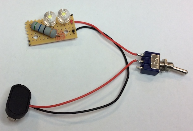
- This is an example of a stripboard circuit. A few important points have been picked out, which you might want to consider in your design.
- Strain relief holes only take a few seconds to drill, but will prevent your power wires from breaking off again and again.
- 3mm holes in the PCB will allow you to poke M3 machine screws through them to secure the lights at the bottom of your housing.
- The spot-face cut is to prevent the steel nuts we use from creating a short-circuit and burning out your LEDs.
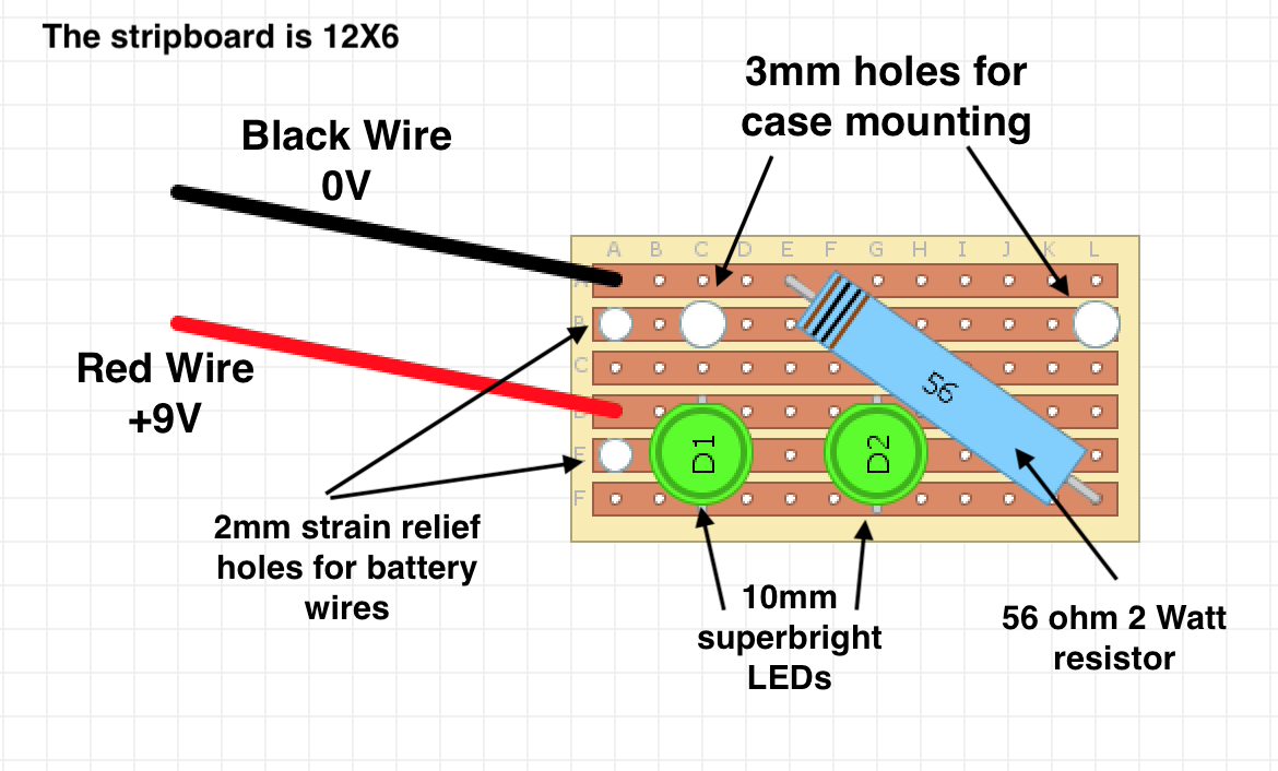
- You are seeing the finished circuit from the component side (the side with no copper tracks on it).
- To make life a little easier, the tracks are also shown (as if you had X-ray vision).
- Here you can see the path that electrons take through the circuit. Remember that the electrons are unable to jump over the thin gaps between the copper rows of stripboard.
- Electrons travel in from the red wire, arriving at the middle row of the stripboard and attacted towards the negative end of the battery (black wire).
- As the only route they are presented with is to travel through the + leg of the LED, they pass through here and emerge at the bottom.
- From here, the only route the elctrons can take now is to travel through the 2W resistor, to the top row of the piece of stripboard.
- Once at the top row, the electrons are able to travel up the black wire to the negative terminal of the battery, completing the circuit.
Badge It
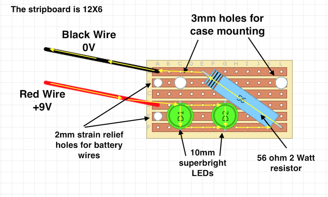
- Using the example circuit provided to you above, use DIYLc to create the circuit shown above on a stripboard.
- Tip: When inserted in stripboard, the LEDs occupy 3 columns and 3 rows.
- Tip: You'll need to keep two 3mm holes to mount your PCB to the housing. Remember that creating a hole in a row of this size prevents current from travelling past that point in the row.
- You will be awarded a badge for your work :
- Silver: All components added to stripboard design.
- Gold: Workable final design is 16x7 or under.
- Platinum: Design is 12x6 or under.