GENIE chips can be programmed with several configurations.
We'll need 1 pin to provide power to the chip and 1 pin to tie it to ground.
We'll need 1 pin to program the chip.
We'll need 1 pin to receive an input.
This leaves us with 4 pins to play with.
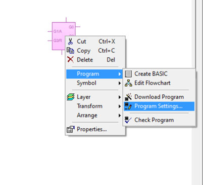
By right clicking on the GENIE chip in Circuit Wizard, we can choose >Program>Program Settings
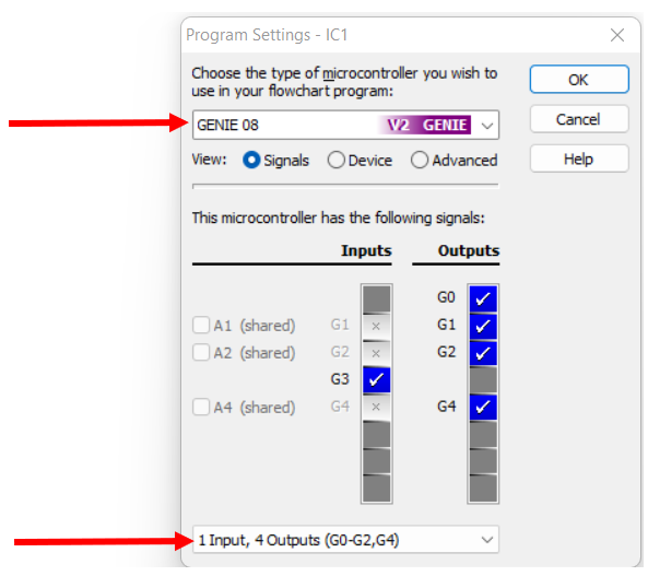
In the bottom drop box, you need to change it to 1 input, 4 outputs (G0-2, G4) - it is the first option.
In the top drop box, make sure you choose the Genie 08 - V2 Genie - see image below.
We're going to want to have as many outputs as possible, so this configuration is probably the best.
Try It
If we want to make a die, we need to be able to represent the numbers 1-6 using LEDs
But we can't simply connect an LED to each output pin, as we only have 4 output pins to use.
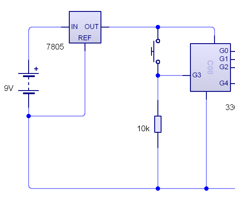
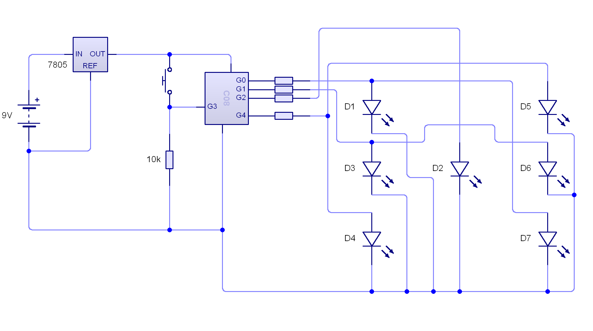
Build the circuit as shown below.
You will find the Voltage regulator (7805) under 'Power supplies' in the drop down menu.
2 A Program for the Die
Try It
We're going to build the circuit shown below to program our Die.
Please note: The resistor on G2 is 330 ohms and the resistors on G0, G1 and G4 are 120 ohms.
You will find the Voltage regulator (7805) under 'Power supplies' in the drop down menu.
It might help you to understand how the outputs control the LEDs by using the simulation below.
Badge It - Silver
Part 1: Use the simulation above to write down which outputs will need to be set to high for each number the die will generate from 1 through to 6.
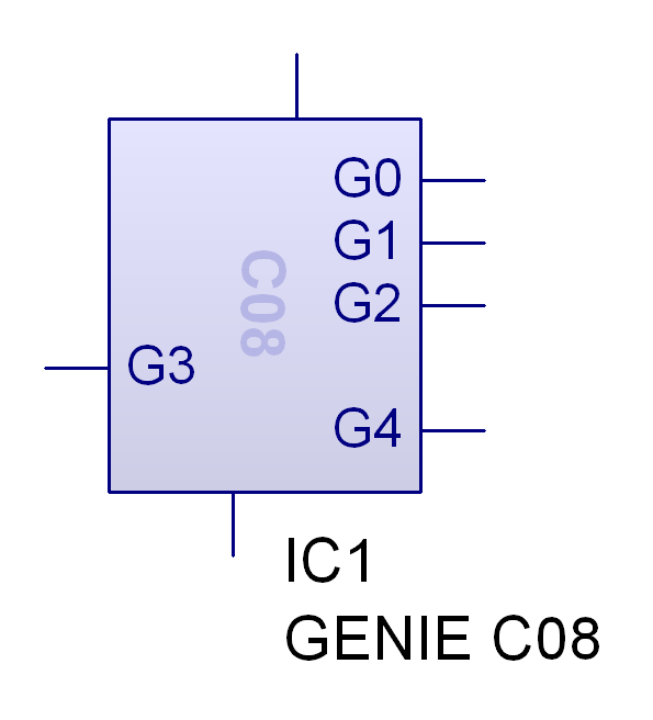
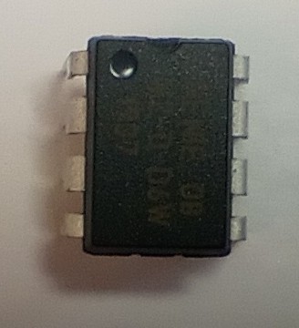
Part 2:The diagramBelow is of a 'real world' Genie 08. The pins are not the same as the circuit wizard symbol (above). Using the diagram below and any graphics package you choose, draw a basic diagram to show how the arrangement of LEDs will be connected to the pins of the 'real world' GENIE 08 IC.
This silver badge progress ladder indigo - Follow a PCB created by a third party, and identify some of the outputs and inputs.
Learn It
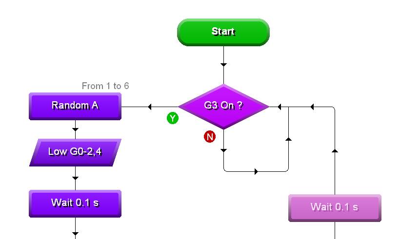
With this information, you should now be able to create a program to generate the random numbers.
You've quite a bit of experience using flowcharts to program GENIE chips already, so here is the start of the flowchart only.
Badge It - Gold
Use the file you downloaded earlier and your knowledge of which outputs to send high to complete the program and test it to make sure it works.
Take a screenshot of your program when you have finished.
This gold badge progress ladder yellow - With assistance, write a simple program to manipulate outputs
Badge It - Platinum
There are many ways of solving this problems.
See if you can come up with an alternative algorithm that doesn't use the Random block.
Take a screenshot of your program when it is complete.
This platinum badge progress ladder, green - With assistance, write programs to handle inputs in a PIC circuit.