| Lesson 1 | Lesson 2 | Lesson 3 | Lesson 4 | Lesson 5 | Lesson 6 | Lesson 7 | Lesson 8 | Assessment guidance | Homework Tasks |
PCB Build
1 PCB soldering
In the last lesson, you looked at the theory of how the circuit works, and wrote a test program for it.
Build It
- Now, we'll start to build your actual PCB. Start by getting the PIC Programmer PCB, and get the resistors and an 8-pin chip carrier.
- You will most likely want to solder the LEDs onto the PCB using fly leads (multi-core wire extensions). Below is a video on how to solder these in place from the 'Door Buzzer' project you did in year 7.
- Solder the resistors in, using the correct soldering technique.
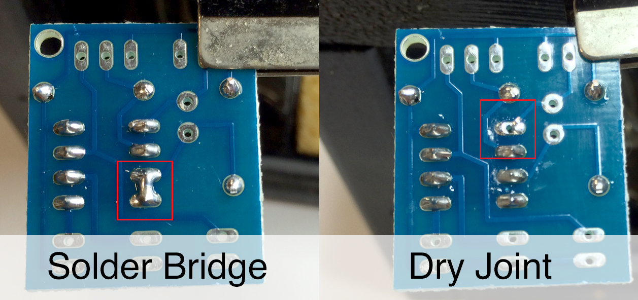
- Now look at your chip carrier. You'll notice there's a notch in one side. You'll notice a matching notch on the outline of the chip carrier on the PCB (labelled 'C08'). Solder this into the board the right way up, and take care to ensure none of the solder pads get soldered to one another (called a solder bridge), or leaving a pad so that the drill-hole is still visible (called a dry joint).
- The picture below shows the soldering faults described above.

- With these in place, you can add the other components in any order.
- Remember to make sure to install the LEDs the right way around. You can use either 3mm or 5mm LEDs of any colour. Note that blue LEDs might not work, as they require slightly more voltage.

- Keep using the side cutter to remove the excess wire from the component legs as you go along, to make it easier to work on the board.
- The LDR is non-polarised, so can be mounted either way round.
- Try and keep all your components flat to the board, so that they're not sticking up in the air.

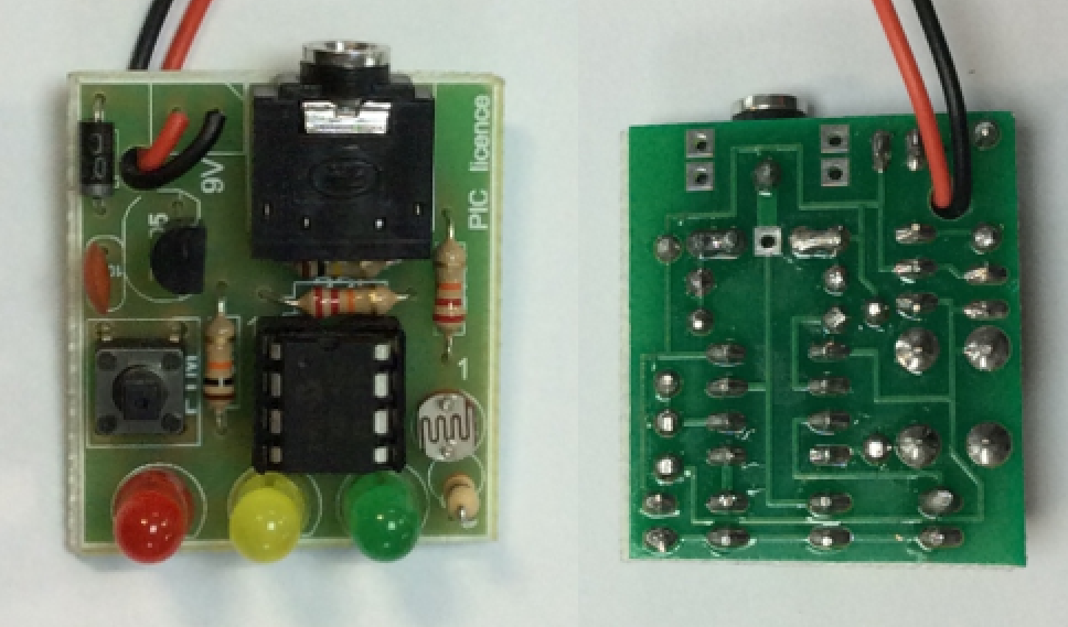
- When you're finished, your board should look something like the image above. However, yours should have fly leads for the LEDs.
- You can now see your teacher for a Genie C08 chip, which you can insert into the chip holder.
- NOTE: Make sure the right way up, by ensuring that the notch in the Genie chip lines up with the notch on the chip carrier.
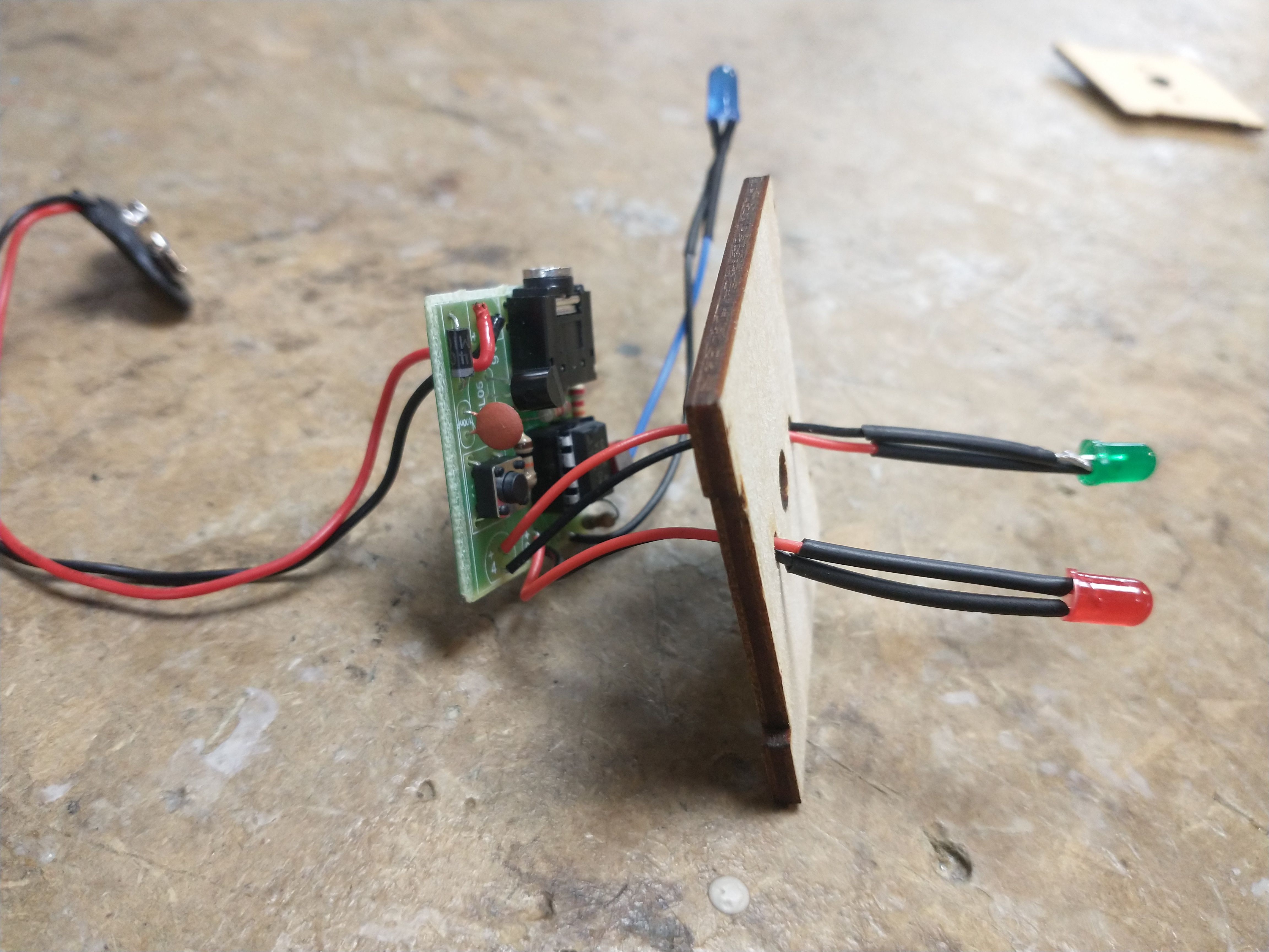
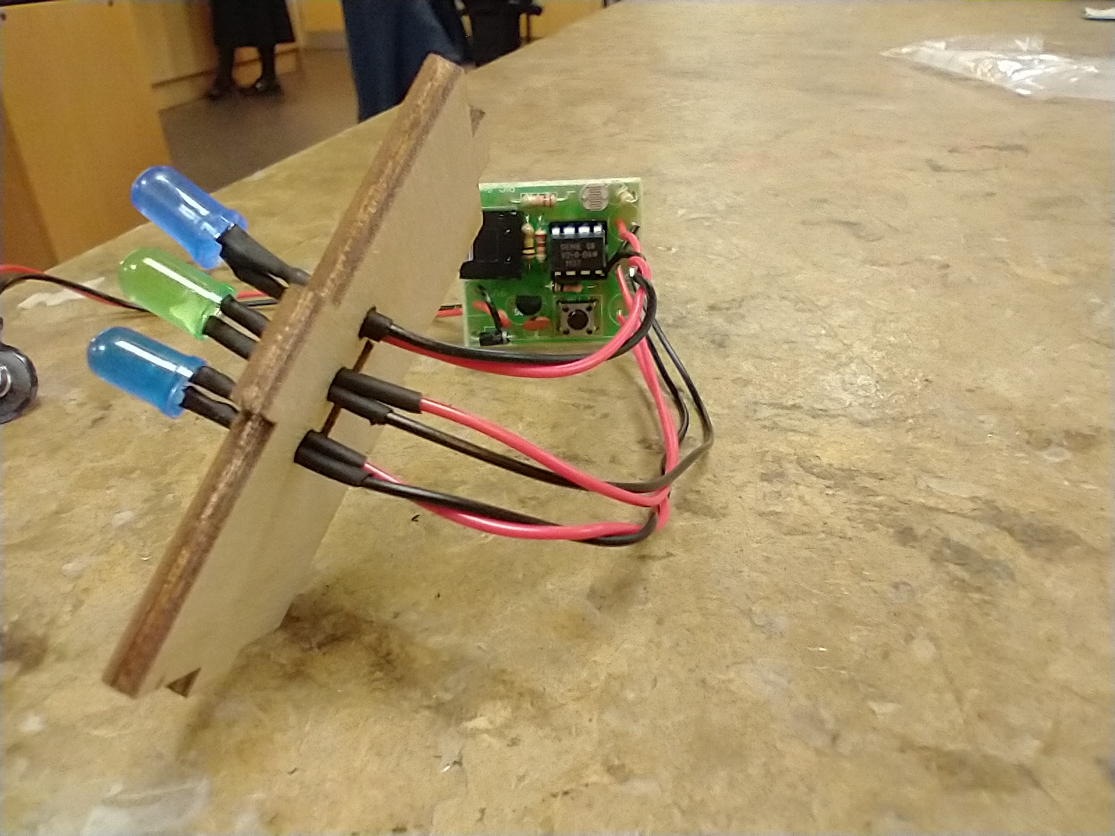
Soldering it though the case:
Elephant style box - two wires through the small holes.

Snowman style box

2 Assessment Point
Badge It
- Take pictures of the following, for inclusion in your portfolio: PCB (front), PCB (back).
- Upload your photos and then create a text document describing your soldering technique, briefly stating what you feel is good about your work, and identifying something you'd like to improve. Upload the text document.
- Silver Badge - Progress ladder, Yellow - Identify and solder simple components (e.g. resistors) to PCBs, with assistance.
- Gold Badge - Progress ladder, Green - Solder more challenging components (e.g. ICs) to a PCB, with assistance.
- Platinum badge - Progress ladder, Blue - Confidently and consistently solder components to a high standard.