| Design Engineering Theory Topics - Home Page |
Mechanical devices used to produce movement
1 Introduction
- The difference between studying Design Engineering and electronics is that you will need to be able to use your circuits to make things happen in the real world. One of the coursework projects you might be asked to complete is a humane mousetrap, for instance. The first thing to understand is the four types of motion…
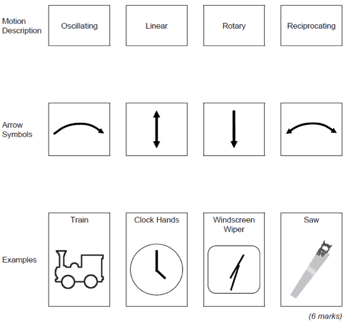
Rotary
- Rotary motion is defined as being, “rotation around a fixed axis”.
- Examples of this could be a drill, a wheel or a desktop fan.
Oscillating
- Oscillating motion is defined as, “repetitive change between two different states”. Examples are windscreen wipers, or a clock pendulum.
Linear
- Linear motion is “motion along a straight line”. Examples are a paper guillotine, or a train travelling along a track.
Reciprocating
- Reciprocating motion is “a repetitive back and forth motion in a straight line”. Examples could be cutting with a saw or a piston in an engine.
2 Levers
Levers are simple mechanisms that create mechanical advantage. They have three parts - effort(input), fulcrum(pivot) and the load(output). There are 3 types of levers.
Class 1 lever
- Examples are the see-saw and pliers.

Class 2 lever
- Examples are the wheel barrow or nut crackers.

Class 3 lever
3 Calculations
Mechanical advantage
- This allows us to exert a large force using a small effort.
- It can be calculated by comparing the weight of the load with the effort required to move it.
For example a wheel barrow(class 2 lever) needs a 50N effort to lift a 300N load. MA = load / effort = 300/50 = 6
- You can find out more about lever calculations by clicking on this link. this is the lever calculations you did in the Year 8 Mechanisms project.
Velocity Ratio
- This is the ratio of the distance the effort has to move compared to the load, in a given time.
- Using our wheel barrow again, the handles are lifted 800mm while the load is only moved 100mm.
- VR = effort distance / load distance = 800 /100 = 8
- Alternatively this can be rearranged to:
- Load distance = effort distance / VR
- Effort distance = load distance X VR
Efficiency
- No mechanism is 100% efficient as other factors, such as friction, will have an impact.
- Efficiency is the relationship between the input force and the movement, and the output force and movement.
- Efficiency = MA / VR X 100% = 6/8 X 100% = 75%
- Therefore the wheelbarrow is 75% efficiency.
4 Cams
- In Year 7 you looked at Cams when making you CAM box project. Click on this link to go back and look over it again.
- Cams allow us to change the type of motion, direction and speed from a rotary shaft.
- They convert rotary motion into reciprocating and oscillating motion.
- The follower is the device that follows the movement of the cam profile to provide the desired output.
- They are three stages of movement - rise (follower moves up), fall (follower moves down) and dwell (follower remains stationary).
- Examples are:
Drop cam(snail) -slow rise and then a sudden fall. Used in hammers or punches to give that sudden drop. Pear cam - dwells half the time and the other half it slows rises and falls. Used in car engines to open and close valves. Eccentric cam - gives a continuous smooth motion as it rises or falls. Used in fuel pump or steam engines.
- Followers can also be different shapes.
- Roller - reduces friction good for higher speeds.
- Knife edge - used for accuracy such as in embroidery machines.
- Flat - used when higher load bearing is required.
5 Pulleys and Belts
- In Year 8 and Year 9 you looked at pulleys and belts and completed all the equations.
- Click on this link to see the Year 8 work.
- Click on this link to see the Year 9 work.
- Pulleys are used to change the speed, direction of rotation, or turning force or torque.
- A pulley system consists of two pulley wheels each on a shaft, connected by a belt. This transmits rotary motion and force from the input, or driver shaft, to the output, or driven shaft.
- A pulley system with one 40mm diameter pulley and a 120mm pulley, connected by a belt. The smaller pulley is rotating at 100rpm
- If the pulley wheels are different sizes, the smaller one will spin faster than the larger one. The difference in speed is called the velocity ratio. This is calculated using the formula:
- Velocity ratio = diameter of the driven pulley ÷ diameter of the driver pulley
- If you know the velocity ratio and the input speed of a pulley system, you can calculate the output speed using the formula:
- Output speed = input speed ÷ velocity ratio
- Velocity ratio = 120mm ÷ 40mm = 1:3
- Output speed = 100rpm ÷ 3 = 33.3 rpm
Torque
- The velocity ratio of a pulley system also determines the amount of turning force or torque transmitted from the driver pulley to the driven pulley. The formula is:
output torque = input torque × velocity ratio.
Pulley drive belts
- Drive belts are usually made of synthetic fibres such as neoprene and polyurethane, with a V-shaped cross section. It is possible to reverse the direction of the driven pulley by twisting the belt as it crosses from input to output.
- Pulley belts have the advantage over chains that they do not need lubrication (though unlike a chain, a belt can slip).
- For more information, click on this link
Calculations
6 Crank and Slider
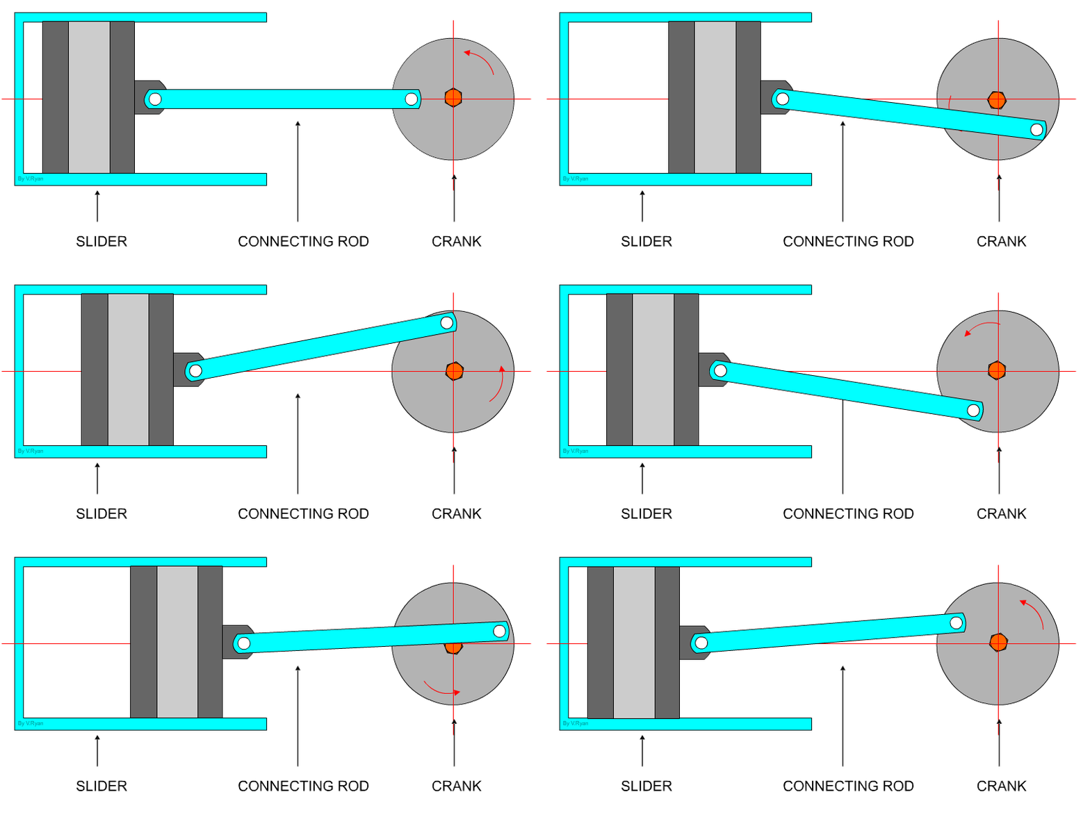
- This mechanism is composed of three important parts:
- The crank which is the rotating disc, the slider which slides inside the tube and the connecting rod which joins the parts together.
- As the slider moves to the right the connecting rod pushes the wheel round for the first 180 degrees of wheel rotation.
- When the slider begins to move back into the tube, the connecting rod pulls the wheel round to complete the rotation.
7 Gear Types
Simple gear train
- You looked at gears in the Year 8 Mechanisms project. Click on this link to see the project.
- The simple gear train is used where there is a large distance to be covered between the input shaft and the output shaft.
- Each gear in a simple gear train is mounted on its own shaft.
- When examining simple gear trains, it is necessary to decide whether the output gear will turn faster, slower, or the same speed as the input gear.
- The circumference (distance around the outside edge) of these two gears will determine their relative speeds.
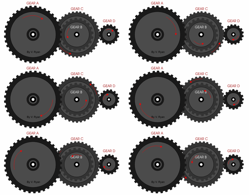
Complex gear train
- A compound gear is a number of gears fixed together. Consequently, they rotate at the same speed.
- The gears that make up a compound gear usually differ in size and have a different number of teeth.
- This is useful if there is a need to speed up or slow down the final output.
- Here is a link to www.technologystudent.com with a great example on how to calculate compound gear sets.
Idler gear
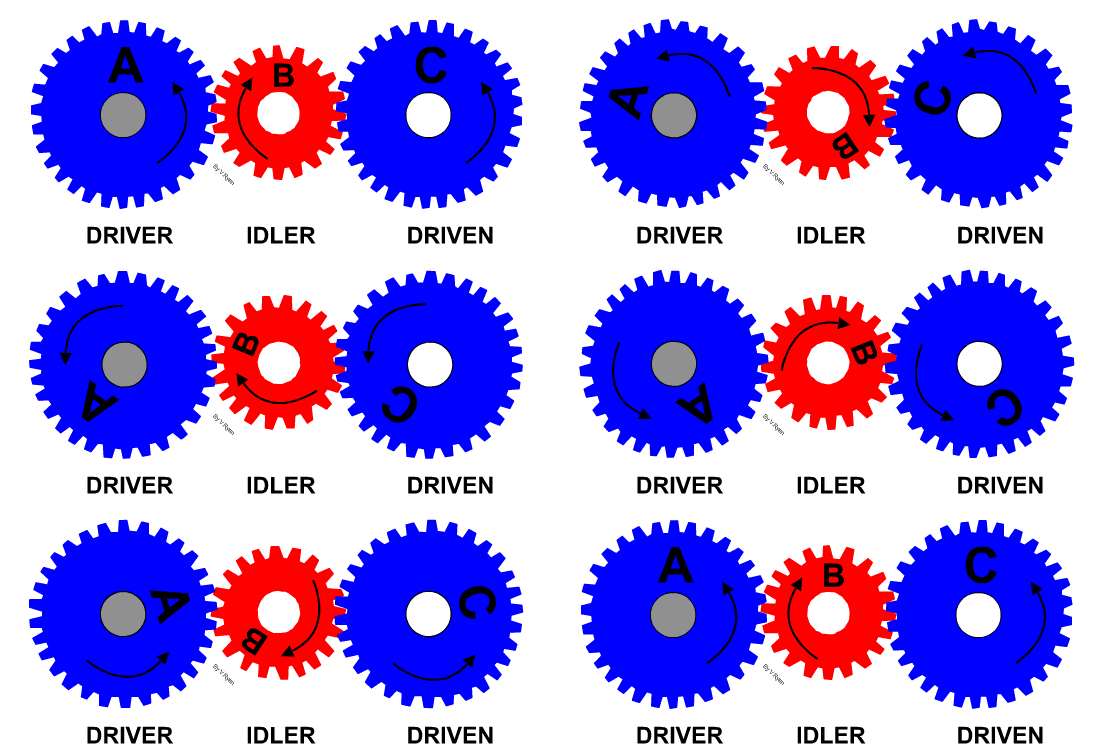
- An idler gear is a gear wheel that is inserted between two or more other gear wheels.
- The purpose of an idler gear can be two-fold.
- Firstly, the idler gear will change the direction of rotation of the output shaft.
- Secondly, an idler gear can assist to reduce the size of the input/output gears whilst maintaining the spacing of the shafts.
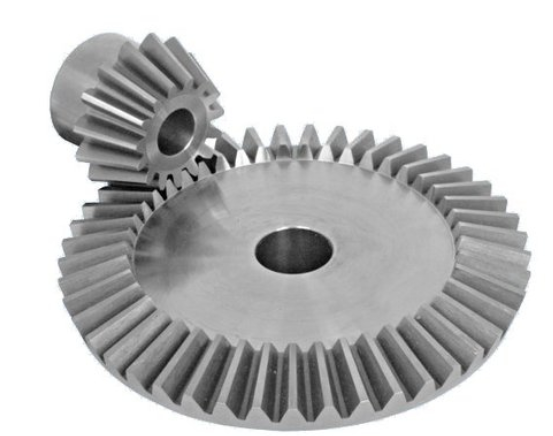
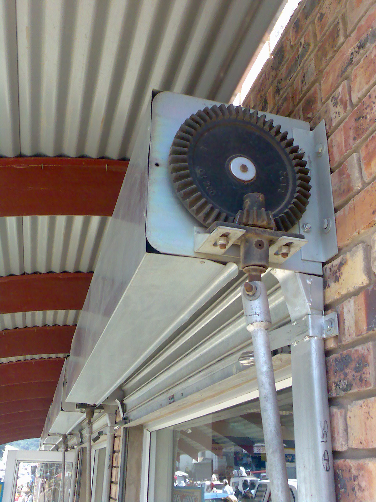
Bevel gears
- Bevel gears are gears where the axes of the two shafts intersect and the tooth-bearing faces of the gears themselves are conically shaped.
- Bevel gears are most often mounted on shafts that are 90 degrees apart, but can be designed to work at other angles as well.
- The pitch surface of bevel gears is a cone.
Rack and pinion
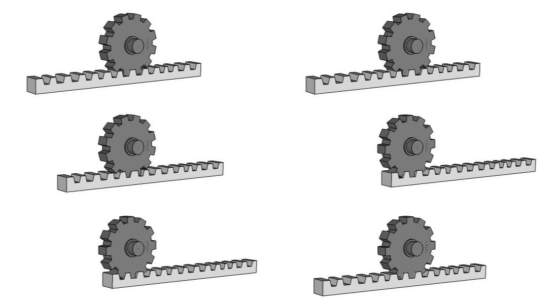
- A ‘rack and pinion’ gears system looks quite unusual. However, it is still composed of two gears.
- The ‘pinion’ is the normal round gear and the ‘rack’ is straight or flat.
- The ‘rack’ has teeth cut in it and they mesh with the teeth of the pinion gear.
The below video has everything you could ever need to know on gears.
8 Recap
Sample Questions
Task 1: Find two more examples of each type of motion.
In addition to these basic forms of motion, it is sometimes desirable to convert one type of motion into another.
Task 2: Find out how to convert each of the following: -
i) Rotary to Linear,
ii) Linear to Rotary,
iii) Rotary to Reciprocating and
iv) Oscillating to Rotary.
Tip: You may find this site helpful, as well as pages 61 and 65 of the textbook.
Past Paper Questions
June 2012, Q3a. Draw lines to link each motion description below to the correct arrow symbol. Then draw lines from each arrow symbol to the correct example at the bottom of the page.
