It would be convenient if we could just hook a buzzer up to the remaining digital output of the circuit.
Let's try it out.
Test It
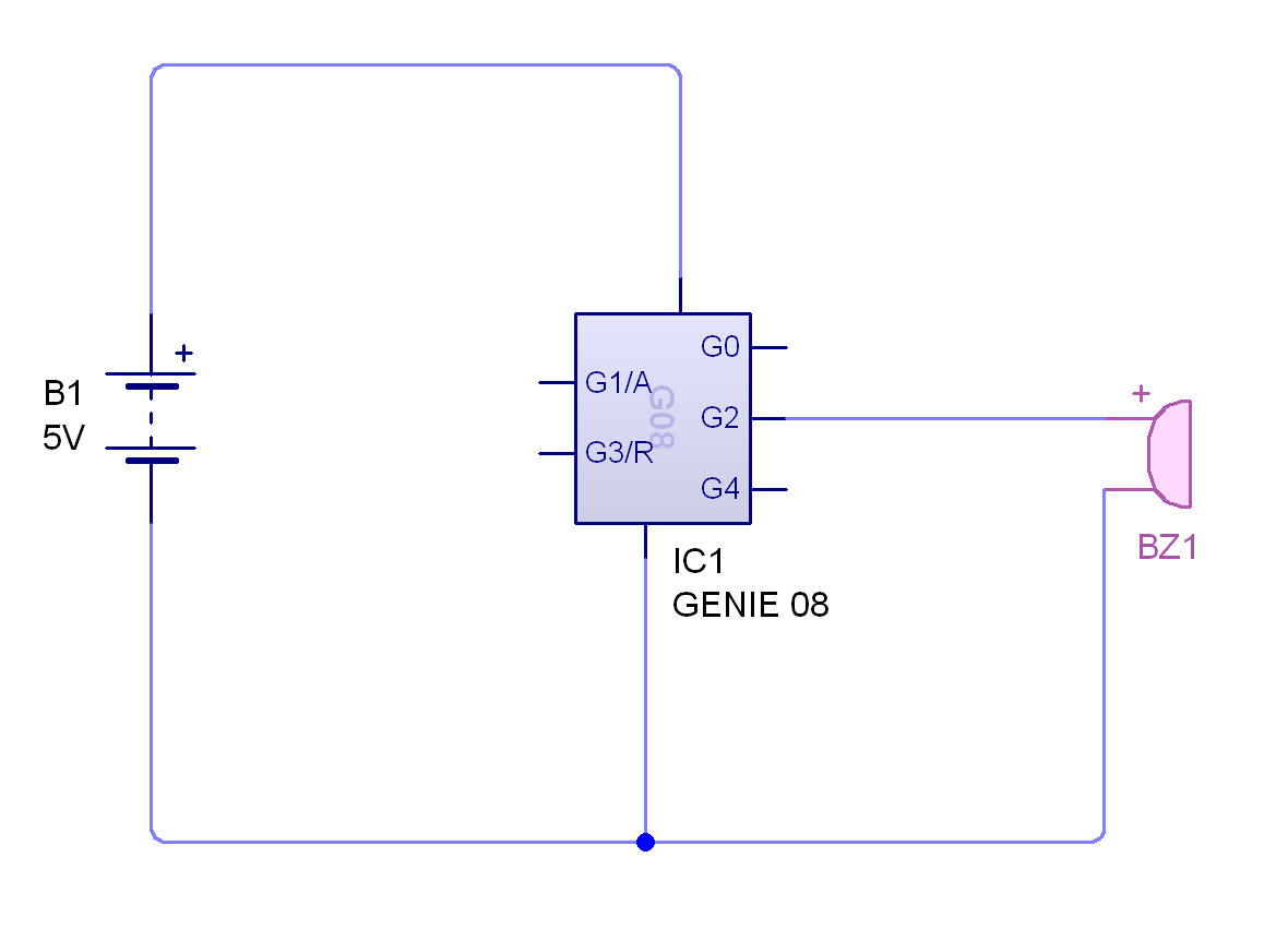
Set up a circuit like the one shown below.
The buzzer can be found under 'Audio' in the gallery.
IC1 is a Genie 08 'microcontroller' in the gallery.
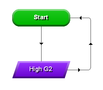
And use a simple program like the one shown below.
Now run the program.
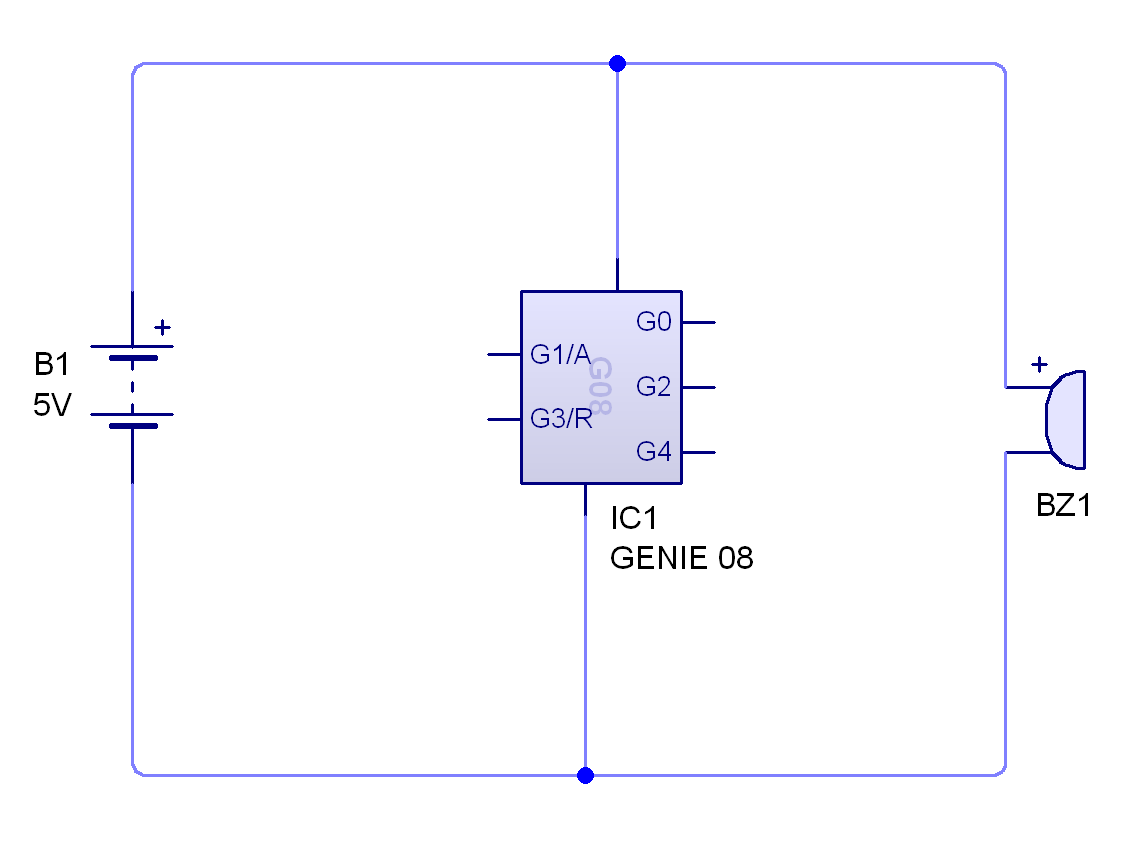
It appears as if the buzzer's not working, but let's just check that it's a problem caused by the GENIE chip and not the buzzer itself.
Draw this circuit and see what happens.
Badge It - Silver
Use a digital voltmeter and try and figure out why the buzzer does not work when connected to a GENIE chip's outputs.
Use screenshots to help explain what is happening.
To understand why the Genie 08 may not have enough current, look at this document.
2 Using a transistor as a digital switch
Learn It
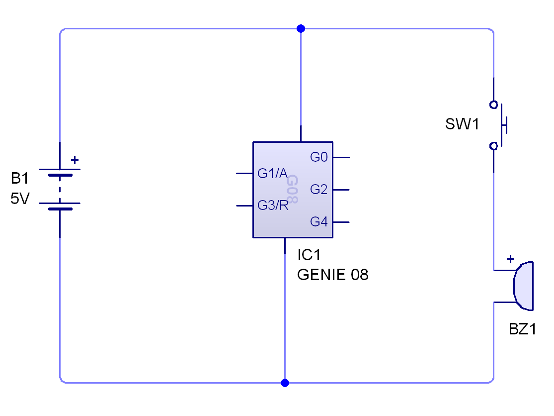
We need a way to connect the buzzer up to the 5V power rail, but still control whether it is on or off.
A simple switch would allow us to do this.
But the switch can only be operated manually, and we need to be able to open and close it using the GENIE chip outputs.
Luckily there is a component that can perform exactly this function. It's called a transistor.
Try It
Transistors have three pins Base, Collector and Emitter.
When there is a voltage at the base of the transistor, current can pass through the collector and emitter.
One thing to remember is that transistors can be sensitive to even moderate currents. It's a good idea to put a resistor between the base of the transistor and the output pin of the GENIE chip. A 1kΩ resistor should suffice.
We'll use a BC547B transistor in the circuit.
Badge It - Gold
You should now be able to complete your circuit.
This tutorial can help if you're stuck…
Please note: C1 is a capacitor which can be found in the 'capacitors' option in the drop down menu.
The voltage regulator (IN-OUT-REF) is under 'Power supplies' right at the top of the options.
To recap - you should have a switch and an LDR on the inputs of the chip, and two LEDs and the transistor that controls the buzzer connected to the outputs.
Screenshot your finished circuit when it is completed.