| Design Engineering Theory Topics - Home Page |
Processes for Fabricating a Prototype

1 Tools and equipment
- An engineer will need to use hand tools to make prototype products.
- These are the most commonly used hand tools used in making working circuits.
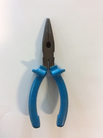
Needle nosed pliers
- Needle-nose pliers (also known as pointy-nose pliers, long-nose pliers, pinch-nose pliers or snipe-nose pliers) are both cutting and holding pliers used by artisans, jewellery designers, electricians, network engineers and other tradesmen to bend, re-position and snip wire. Their namesake long nose gives excellent control while the cutting edge near the pliers' joint provides "one-tool" convenience.
- Because of their long shape they are useful for reaching into small areas where cables or other materials have become stuck or unreachable with fingers or other means.
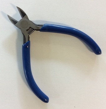
Side cutters
- These are used to cut thin wires and the legs off of components once they have been soldered.
- they have the cutting edge close to the one side so they can cut close to the PCB.
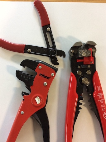
Wire Strippers
- A wire stripper is a small, hand-held device used to strip the electrical insulation from electric wires.
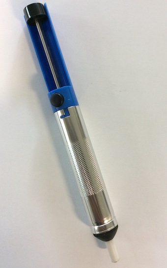
Desoldering pumps
- Also colloquially known as a solder sucker, is a manually-operated device which is used to remove solder from a printed circuit board. There are two types: the plunger style and bulb style. (An electrically-operated pump for this purpose would usually be called a vacuum pump.)
- The plunger type, which we use at school, has a cylinder with a spring-loaded piston which is pushed down and locks into place. When triggered by pressing a button, the piston springs up, creating suction that sucks the solder off the soldered connection. The bulb type creates suction by squeezing and releasing a rubber bulb.
- The pump is applied to a heated solder connection, then operated to suck the solder away.
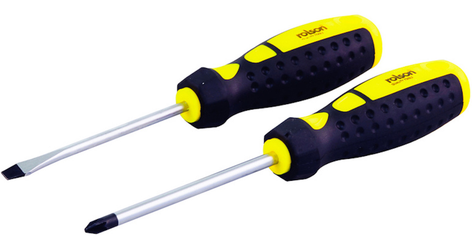
Screwdriver
- A screwdriver is a tool, manual or powered, for screwing and unscrewing (inserting and removing) screws.
- There are many different types of screwdriver, the most common are:
- The Phillips head (this is a cross head or pozidriv)
- The flat head.
- Torx
- Hex
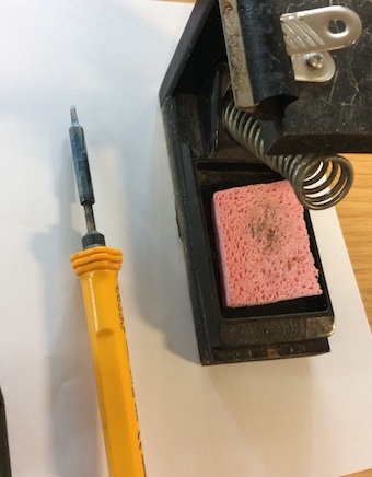
Soldering Iron
- A soldering iron is a hand tool used in soldering. It supplies heat to melt solder so that it can flow into the joint between two workpieces.
- The solder wire is an alloy of tin and lead and melts at around 180 degrees. The tip of the soldering iron heats up to around 300 degrees.
- This temperature is too low to damage the PCB in the short term, but if held there long enough will damage it. The PCB can handle up to around 1000 degrees!
2 Machinery
CNC Milling
- CNC milling is the machining process of using rotary cutters to remove material from a workpiece by advancing (or feeding) the cutter into the workpiece at a certain direction.
- In electronics, we can use a CNC milling machine to cut tracks into a blank copper PCB. The machine will remove any excess copper, leaving only the necessary tracks.
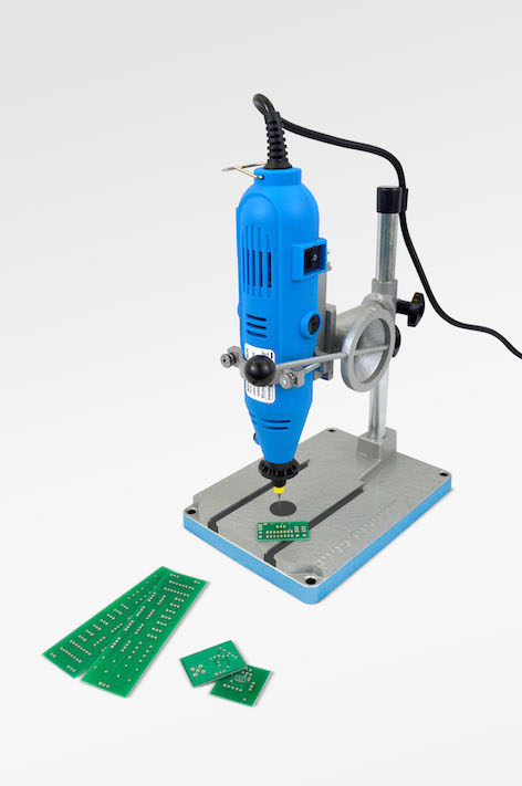
PCB Drilling
- As the PCB holes are usually drilled at 1mm, this requires a more accurate drill that can hold the small drill bit.
- A standard pillar drill will not be able to close enough to hold a 1mm drill bit.
- PCB drill are used for this.
Digital design and manufacture
- Computers are used to design (CAD) and manufacture PCBs.
- We use Circuit Wizard to design and manufacture our PCBs.
- Circuit Wizard allows us to:
- Simulate the circuit to get a good idea if the circuit will work.
- Design and test (simulate) the PCB.
- Print off the PCB designs for manufacture.
- We also use SolidWorks to produce 3D models of the products we are going to make.
- SolidWorks alows us to:
- Design a 3D model of the product to test the parts will fit.
- Send the design to a CNC machine such as a laser cutter or 3D printed for manufacture.
- Advantages of computer modelling:
- You can test ideas without spending any money on parts.
- CNC machines can cut out parts more accurately and quickly.
-
Accuracy
- more accurate designs than manual drawings
- can create designs with millimeter accuracy
- can calculate how multiple materials relate
Efficiency- can reduce the time it takes to design and manufacture products
- can automate many design tasks, reducing design effort
- can integrate with CNC turning and milling plants, making the most efficient use of machines
Productivity- can increase productivity by saving time
- can reduce project completion time
- can help designers create complicated designs quickly and precisely
Collaboration- can be used for cloud collaboration, allowing multiple people to work on the same design from different locations
- makes it easy to share designs with others for feedback
Simulation- can be used to test the strength of a 3D model when forces are applied at different points
- Disadvantages:
- Costs Initial costs: New CAD systems can be expensive to purchase
- Training costs: Training staff to use CAD software can be costly and time-consuming
-
- Maintenance costs: Software and operating systems may need to be regularly updated, which can be expensive
Security risks- Viruses: CAD work can be vulnerable to viruses
- Hacking: CAD work can be vulnerable to hacking
Learning curve- Time to learn: It can take time to learn how to use CAD software
Other disadvantages- Hardware failure: Computer breakdowns can lead to lost work
- Staff skills: Training may be required to use CAD software
- Employment: CAD/CAM systems may reduce employment opportunities
3 Shaping
Vacuum Forming
- Vacuum forming is a simplified version of thermoforming, where a sheet of plastic is heated to a forming temperature, stretched onto a single-surface mold, and forced against the mold by a vacuum.
- This process can be used to form plastic into permanent objects such as turnpike signs and protective covers.
- Normally draft angles are present in the design of the mold (a recommended minimum of 3°) to ease removal of the formed plastic part from the mold.
- There is one in DE1 - ask to see it in use!
CNC Laser Cutting
- Laser cutting is a technology that uses a laser to cut materials, and is typically used for industrial manufacturing applications but is also starting to be used by schools, small businesses, and hobbyists. We have three at school!
- Laser cutting works by directing the output of a high-power laser most commonly through optics. The laser optics and CNC (computer numerical control) are used to direct the material or the laser beam generated.
- A typical commercial laser for cutting materials involved a motion control system to follow a CNC or G-code of the pattern to be cut onto the material.
3D Printing
- A drawing is made using 3D modelling software (SolidWorks) and then converted into a .stl file (StereoLithography file) which can be sent to the 3D printer for manufacture.
- 3D printing is any of various processes in which material is joined or solidified under computer control to create a three-dimensional object with material being added together (such as liquid molecules or powder grains being fused together).
- 3D printing is used in both rapid prototyping and additive manufacturing (AM). Objects can be of almost any shape or geometry and typically are produced using digital model data from a 3D model or another electronic data source such as an Additive Manufacturing File (AMF) file (usually in sequential layers).
- There are many different technologies like stereolithography (SLA) or fused deposit modeling (FDM). Unlike material removed from a stock in the conventional machining process, 3D printing or AM builds a three-dimensional object from computer-aided design (CAD) model or AMF file, usually by successively adding material layer by layer.
Drilling
- Drilling is used to make a round hole in a materials.
- There are many different types of drills, here are some:
- Hand drills (battery operated and corded)
Weight:- Cordless drills are heavier than corded drills because of the battery and motor.
- This extra weight can cause fatigue, especially when working for long periods or in awkward positions.
Battery life:- Cordless drills have limited battery life, which can vary depending on the brand, model, and how you use it.
- You might need to recharge or replace the battery during long projects.
- It can be expensive to replace batteries.
Cost:- Cordless drills are generally more expensive than corded drills.
- You might need to buy a backup battery in case yours dies during a job.
Power- Cordless drills generally have less power than corded drills.
-
You might need to switch to a corded drill for long periods of continuous use or high-intensity operations
-
2. Pillar drills (floor standing).
-
3. Bench top drills.
-
- Hand drills (battery operated and corded)
- Drills will cut a hole at 90 degrees to the work surface.
- It is possible to cut other shapes using a drill, this is called chain drilling.
4 Fabricating, constructing and assembling
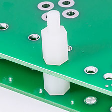
PCB mounting methods
- Once you have made a PCB with all of its components attached it will need to be mounted into a case.
- You can not leave the PCB to rattle around in a case as this could lead to short circuits or damaged components.
- This will also help the product look more professional.
- When mounting a PCB you will need to remember the bottom of the PCB has soldered joints and tracks, this will need to be raised above the surface so as not to cause short circuits and damage, especially when the case is a metal construction.
- The most common way to mount a PCB is to use screws and plastic spacers to raise the board.
- Holes will be drilled in the appropriate places and the board will be screwed in place.
- There are ready made plastic mounts and fixing available, especially when it come to mass production.
Cable Management
- When producing a PCB there will inevitably be a lot of wiring. This will need to be managed safely and neatly.
- Loose cable will move around and can become dislodged and prevent the product from working, or even worse, cause a short circuit.
- We also need to consider whether the cable needs to move or not.
- Cable ties are a very good way of neatly managing cables, there are however, many other cable management systems.
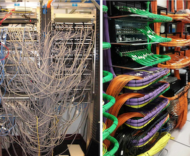
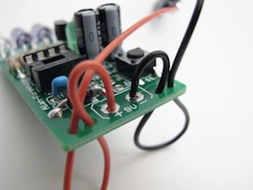
- We also don't want a cable to be soldered directly to a PCB as this will create a weak point and the wire will most likely break loose.
- To prevent this we drill strain relief holes which allow the wires/cable to run from under the PCB, making the stress move from the soldered joint.
- It is also a good idea to colour code cables to make them easier to identify after soldering and running the cable.
- A wiring loom is a bundle of wires and cables that are bound together to transmit electrical power or signals. Wiring looms are also known as wiring harnesses or cable assemblies.
How do wiring looms work?
- Wiring looms are used in complex products like vehicles and household appliances.
- They make it easier and faster to install complex cabling.
- The wires are secured against vibrations, abrasions, and moisture.
- The wires are bundled into a non-flexing bundle to save space and reduce the risk of short circuits.
- The wires are often bound into a flame-retardant sleeve to reduce the risk of electrical fires.
How are wiring looms constructed?- The wires are linked together using straps, cable ties, sleeves, electrical tape, conduit, and weave.
- The sheath is made of a durable material such as rubber, vinyl, electrical tape, conduit, or a weave of extruded string.
- The cables are typically made of copper or aluminum and are insulated with a plastic or rubber coating.
- Wiring looms are used in complex products like vehicles and household appliances.
-
Sleeving, also known as sheathing, is used to protect and organize wires, cables, and hoses. It can also insulate and improve the appearance of cables.Uses
- Protection: Shields cables from damage caused by abrasion, chemicals, UV light, moisture, and extreme temperatures
- Insulation: Protects cables and hoses from high temperatures
- Organization: Bundles cables and wires into neat looms
- Space optimization: Reduces bulkiness and optimizes space
- Aesthetics: Improves the appearance of cables
Types of sleeving- Insulation sleeving: Used for thermal protection in high temperature environments
- Braided sleeving: Protects wires, cables, or hoses from abrasion, chemicals, and UV light
- Earth sleeving: Protects cables from fungus growth and makes cables safer from view
Wastage
- This is the process of removing any excess materials.
- When you have soldered in the components, you will cut off the excess component legs to make the PCB smaller and prevent shorting.
- The PCB can also be trimmed down to remove excess board. Hand tools will be used to do this, such as a saw or drill.
- Some products can be recycled. If you are turning on a lathe or cutting in a milling machine. The metal swarf can often be collected and recycled and then reused.
- This could save you money.
Addition
- Addition is the process that puts materials together to form the required shapes.
- Materials can be cut into shapes with hand tools and fixed together with joints, adhesives (glues), mechanical fixings (screws, nuts and bolts, rivets), and by heat, including soldering, brazing and welding.
- 3D printing is also an addition process, because plastic is added to build up the required design.
- Addition is an efficient use of material, as pieces are cut to the right size with little wastage.
- There are often lots of joins between pieces of materials so it is difficult to make the product strong.
5 Practise Questions
- Name 3 hand tools that will be useful in making prototype PCBs.
- Suggest 2 things a computer could help with when designing or making electronic products.
- Give an example of a product that would be created using a vacuum former.
- Find out the best technique for soldering a joint with a soldering iron, describe the process.
- Give an advantage of wastage and an advantage of the addition process.