555 Astable Multivibrator
1 Introduction
- You can find DIYlc here on the open drive G:\Design Engineering\Student Home software\DIYlc.
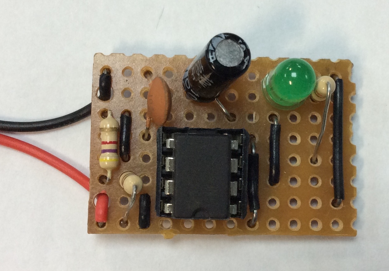
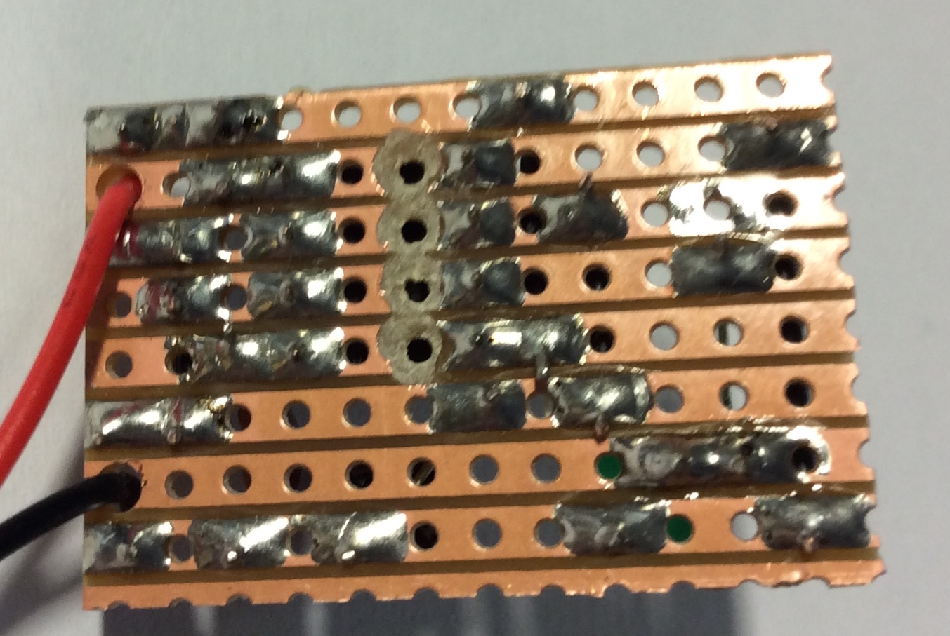
- below is an example, but you can create your own design.
- Once you have designed your board, you can get a piece of veroboard and cut it to size, by counting the holes on your own design.
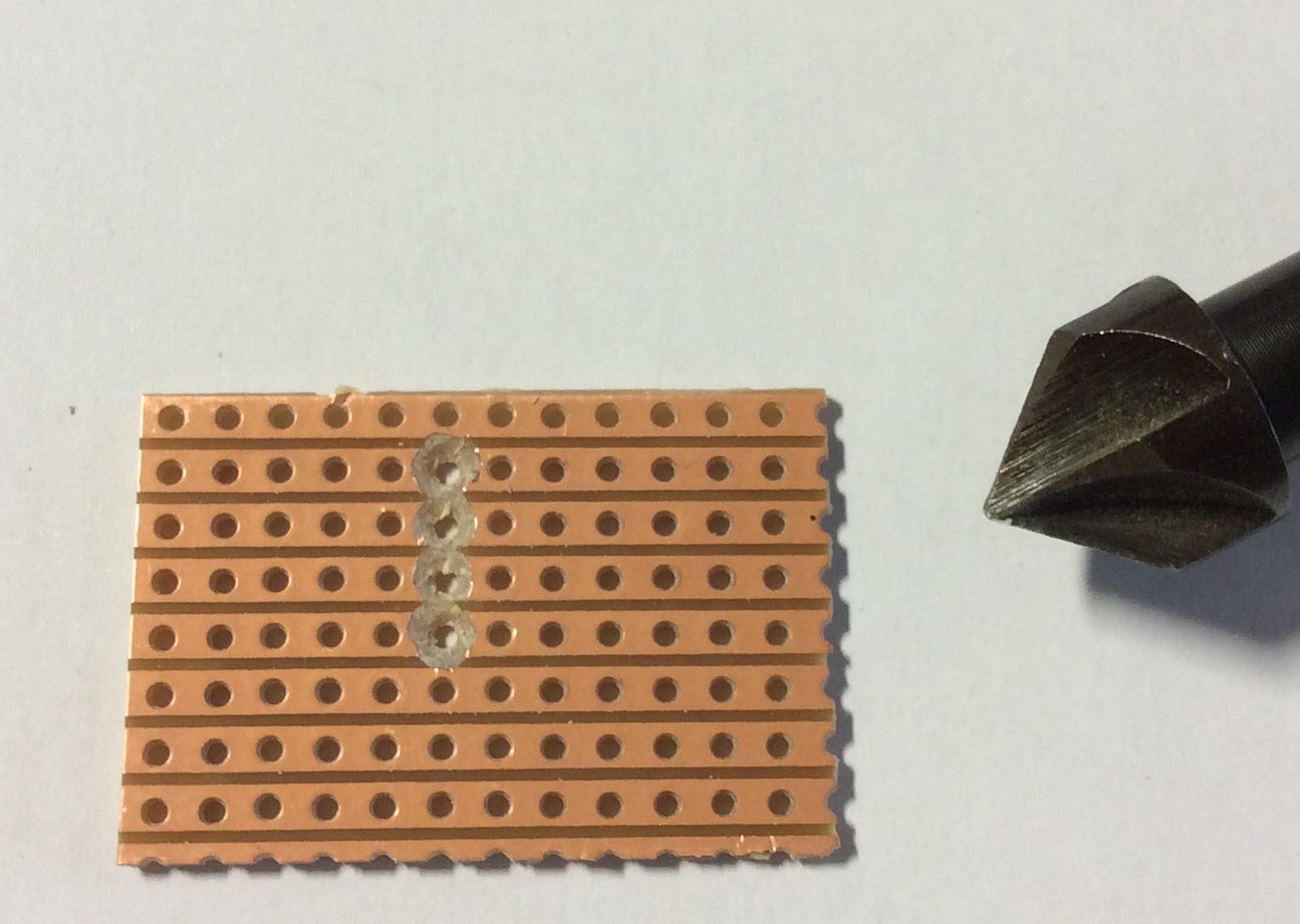
Breaking the tracks
- Before you can solder or place your components, you need to prepare the veroboard.
- First, you will need to break the track under the 555 IC. This can be done using a track break or using a countersink tool as shown below.
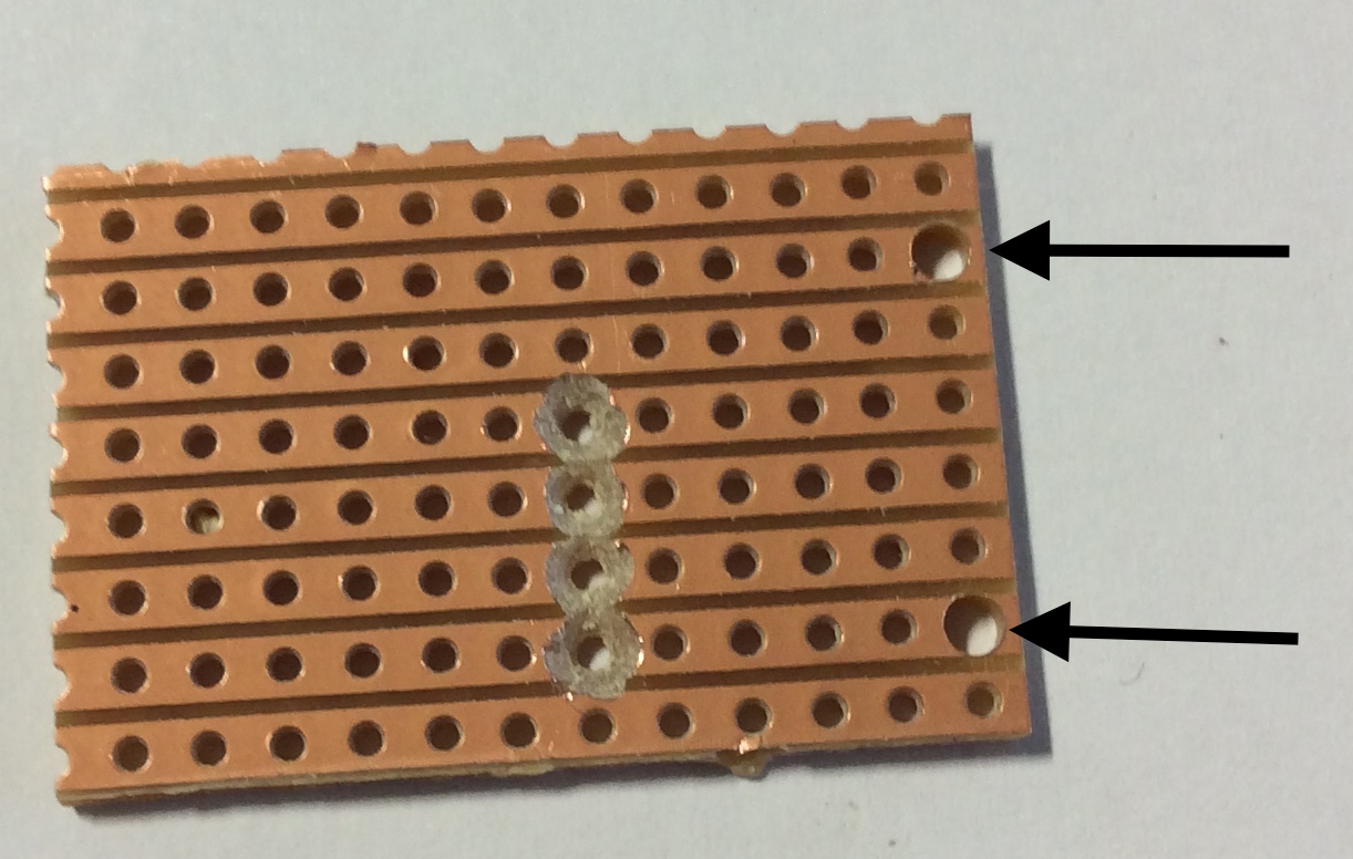
- You will now need to drill 2 holes for the battery wire using a 2mm drill bit.