| Lesson 1 | Lesson 2 | Lesson 3 | Lesson 4 | Lesson 5 | Lesson 6 | Lesson 7 | Lesson 8 | BBL Tasks | Achievements |
Resistors and PIC Carrier
1 Soldering Resistors
In the last lesson, you looked at the theory of resistors, and soldered your first component. We'll now be able to add our resistors, and something called a chip carrier.
Build It
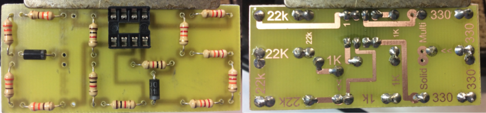
- Go to the component racks and take 1 X 330 ohm resistor, place it in the top left hand position. - Now get your teacher to check it is in the right place before soldering.
- Once it has been soldered, get your teacher to check it again.
- You can then go back to the component racks and take out the following resistors, you'll be using. The values you need are: 3 X 330, 4 X 1k, 5 X 22k.
- You should now be able to identify which is which by their coloured bands. Start with the 330 Ohm resistors, poking the wire legs through the hole above and below the number 330 on the PCB. Remember that the component should sit on the top of the board (with no writing on it), and the legs should stick out of the side with the tracks and pads on. Resistors can be soldered in either way round, but it looks more professional if all the gold bands line up, like mine to in the photo below.
- Make sure the resistor is laying flat against the board, then gently angle the legs out at 45 degrees to stop the component from falling out of the board while it's being soldered.
- Just like before, put the board in the bulldog clip on the soldering iron stand to hold it steady, solder the two legs and then use a side-cutter to trim them.
- Repeat this process for the other resistors.
- NOTE: It is vital that you don't allow solder to flow across gaps on the PCB. If you study the image above, you'll see red rectangles drawn around the areas where you'll need to be careful about this.
- When you're finished, you should have a board that looks like the one in the picture.
2 Chip Carrier
Build It
- More advanced projects that yimages/Soldering_license/ou will make require silicon chips to be inserted into them. The chips themselves don't like heat, and will break if a soldering iron is used on them. To get around this, plastic sockets called "chip carriers" are used to avoid the need to heat the chips up.
- Fetch an 8-pin chip carrier form the component racks, and look at it carefully. There's a notch on one end but not on the other - all chips also have a corresponding notch that is used ot ensure the chip is inserted the right way up.
- Your chip carrier will go in with the notch facing towards the 22k resistors on the board. Put it on the board, then place the board on a cutting mat, balanced on the chip carrier.
- Solder a corner first, then the opposite corner. Check that your carrier is sitting flat against the board before soldering the other pins.