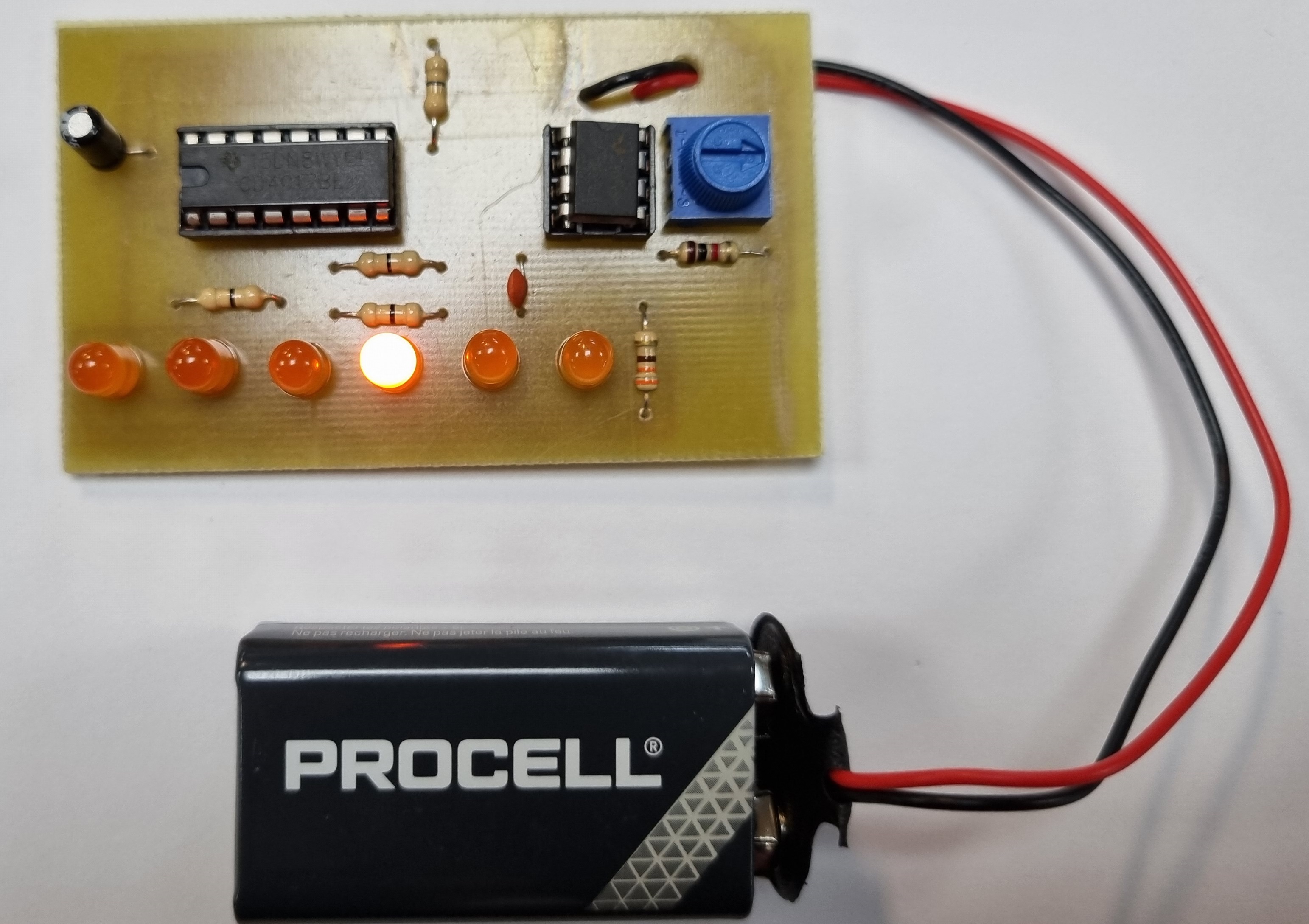
LED Chaser Circuit
1 Introduction
Learn It
Make It
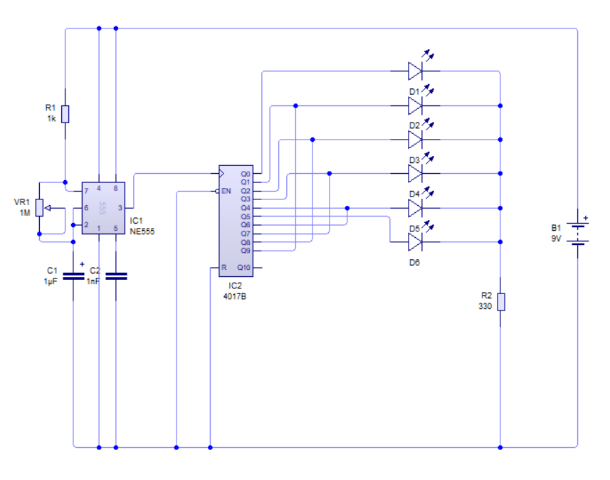
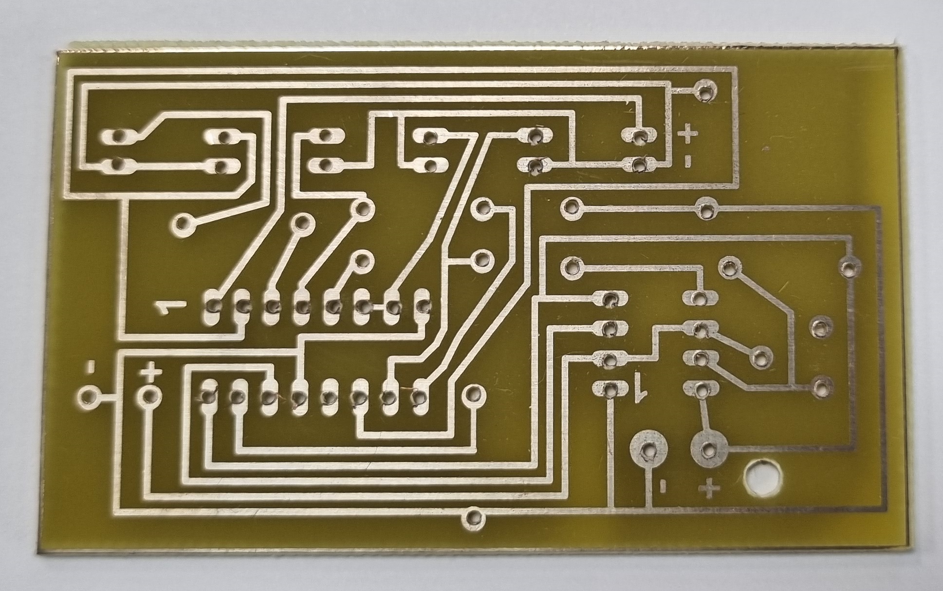
- You below is the circuit diagram and PCB design. You can create your own Circuit Wizard file and design these circuits.
- Note: The 555 timer can be found in the 'Integrated Circuits' menu in Circuit Wizard.
- Note: The 4017 decade counter can be found in the '4000B Series' menu in circuit Wizard.
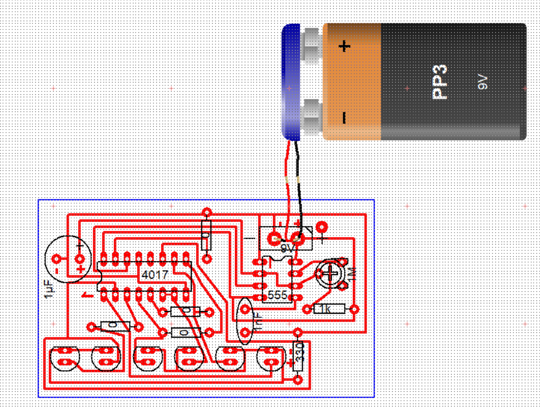
- You will first need to drill the holes using the 1mm PCB drill you used for the soldering license project.
- Click here to remind yourself of the safety precautions.
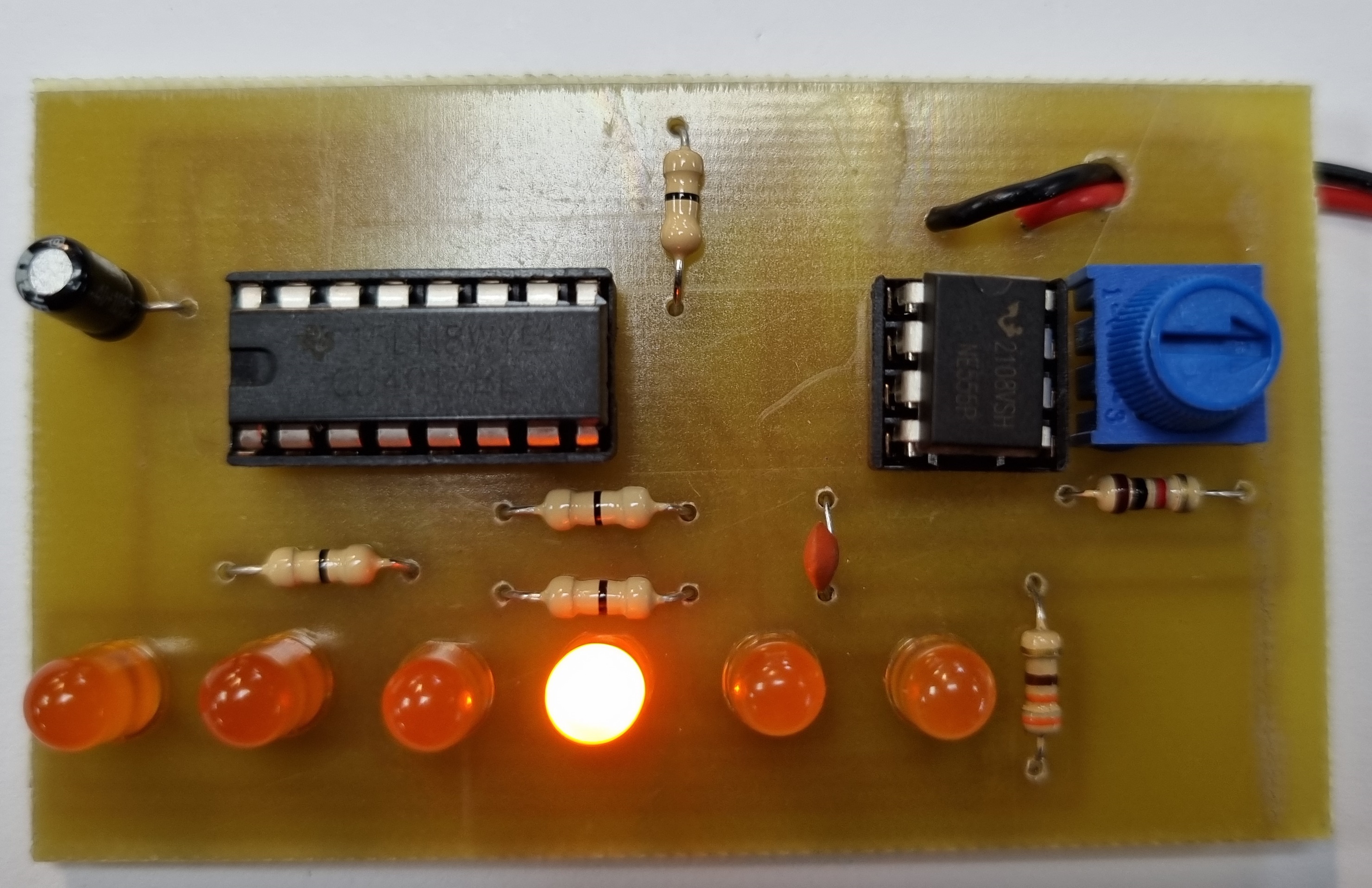
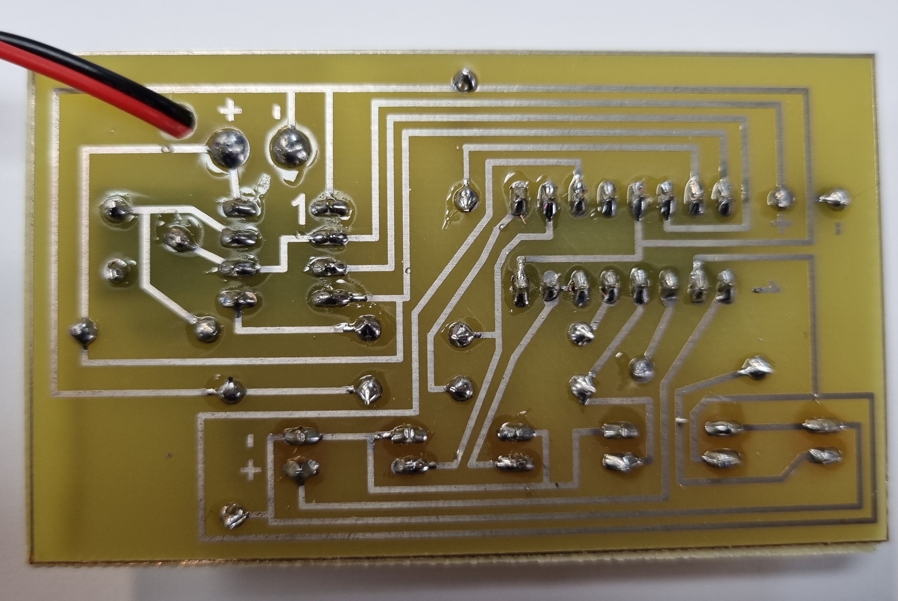
- You can now solder in all of the components, see images below (please note the chip carriers are soldered to the board without the 555 timer and 4017 plugged in).
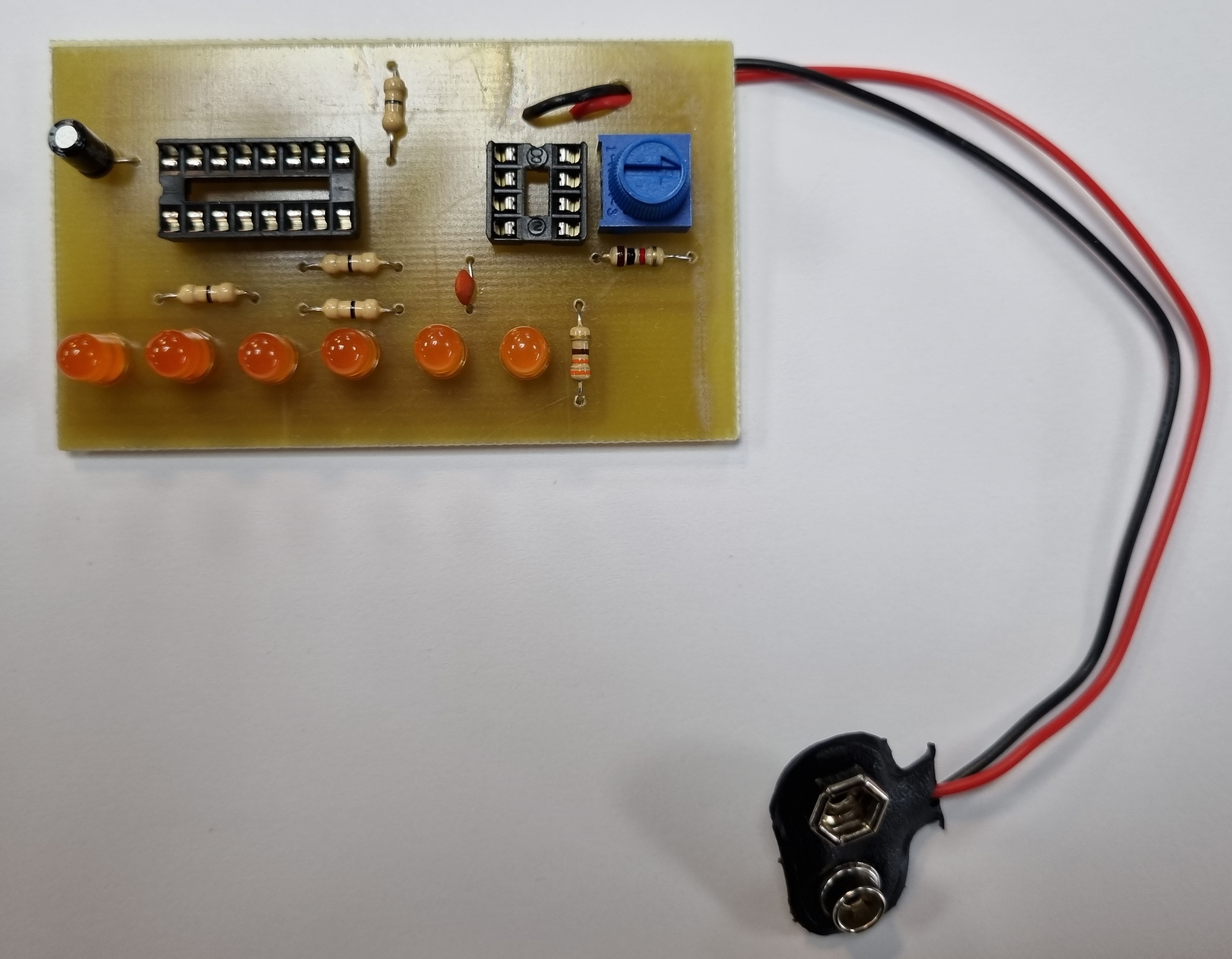
- You now need to plug in the 555 timer and the 4017 decade counter.
- Connect a battery and the circuit should run. By adjusting the potentiometer (the blue component), you can speed up or slow down the speed at which the LEDs move.
