| Week 1 | Week 2 | Week 3 | Week 4 | Week 5 | Week 6 | Week 7 | Additional SolidWorks help | BBL tasks | Assessment guidance |
A Project Storage Box
1 Part-y time
- Now that you've had some experience dimensioning and trimming Solidworks sketches, we're going to create a sketch of our own.
Design It
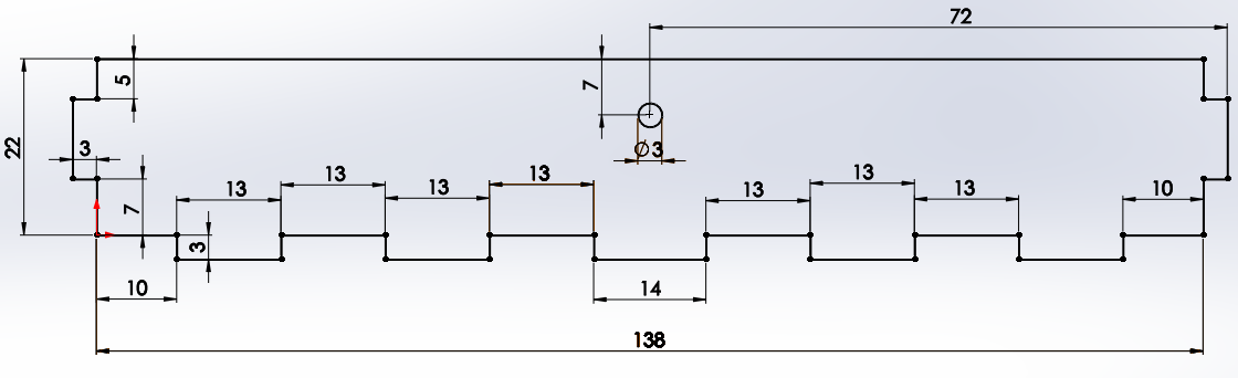
- Here is a picture of the piece we're trying to make.
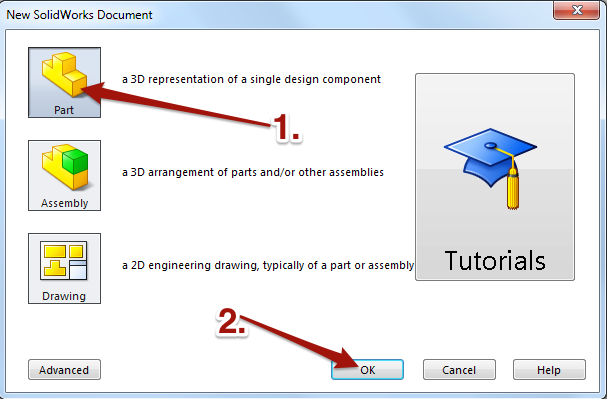
- Open up Solidworks and create a new file.
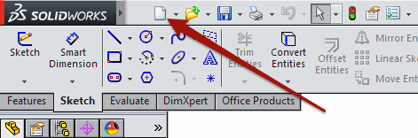
- Choose the option to make a
Part. - Click
OK.
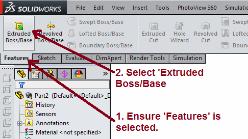
- Ensure the 'Features' tab is selected, then choose 'Extruded Boss/Base'.
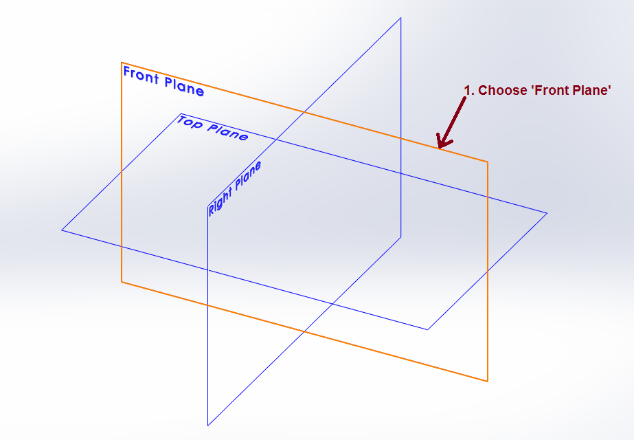
- Now Solidworks will ask you to choose which
Planeyou want to start your sketch in. We'll choose theFront Planeby clicking on it.
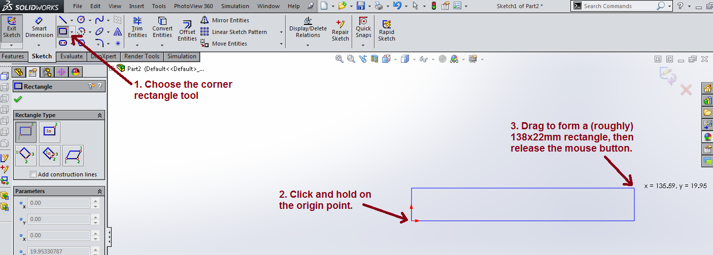
- Ensure the 'Sketch' tab is selected, then locate the
Corner Rectangletool. - IMPORTANT: Whenever you start a new sketch, the very first shape you draw must start on the red 'origin' point to allow it to be fully defined. You'll notice a little orange circle appears as you hover your mouse over the point. Once here, click and hold the left mouse button.
- Drag the mouse up and to the right until the rectangle is approximately 138x22mm. We're going to add dimensions later, so you don't need to be too accurate.
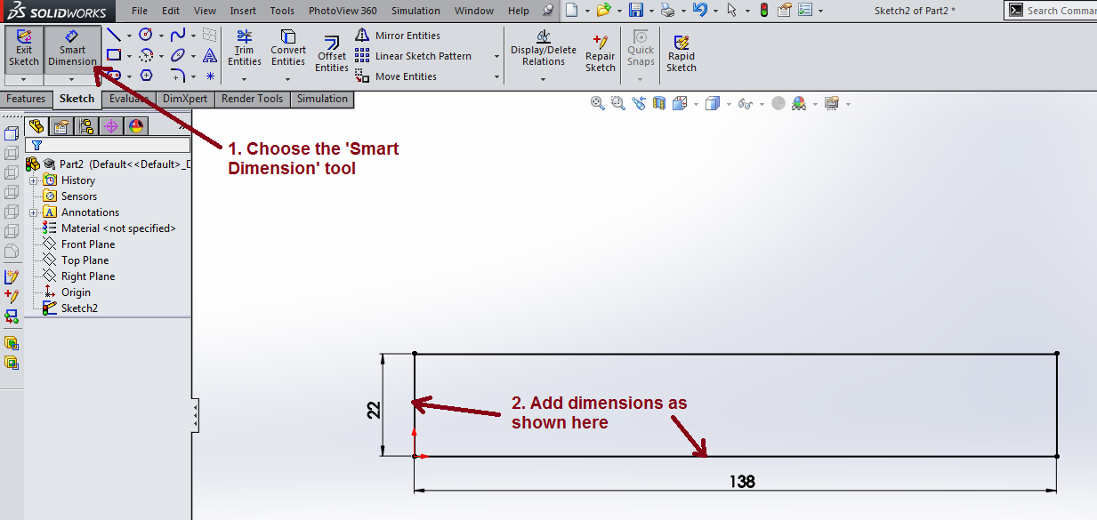
- Choose the 'Smart Dimension' tool.
- Set the width to 138mm, and the height to 22mm.
- CHECKPOINT: In the bottom-right hand corner of the screen, you should see the words, 'Fully Defined'. If not, re-check you've followed all the steps above so far.
- Next we'll add some finger joints.
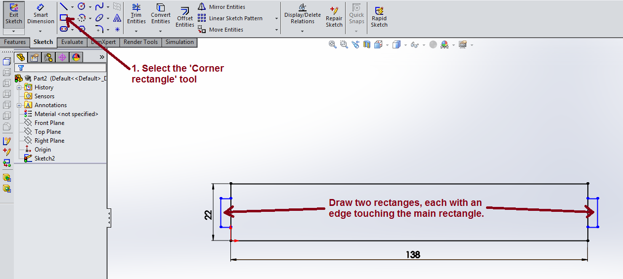
- Select the
Corner Rectangleagain. - Draw two rectangles on the sides of the main rectangle. These are going to be our finger joints. Make sure that one edge of your rectangle overlaps the main rectangle. The size isn't overly important, but aim for 3mm wide and about 10mm tall like in the picture below.
- You should see small green symbols. The first one shown means a point is
coincidentto a line. This is the same as saying it is touching the line. - The second green symbols shown indicate that two lines are
Vertical
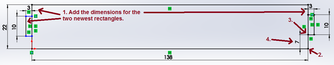
- Add dimensions to the horizontal and vertial edges of both rectangles.
- Click the bottom-right most point in the part (shown below).
- Click the point above it.
- Move the mouse slightly to the left, and click once again. Enter this distance as 7mm.
- Repeat this process under the left-most rectangle.
- Your part will now be fully defined again.
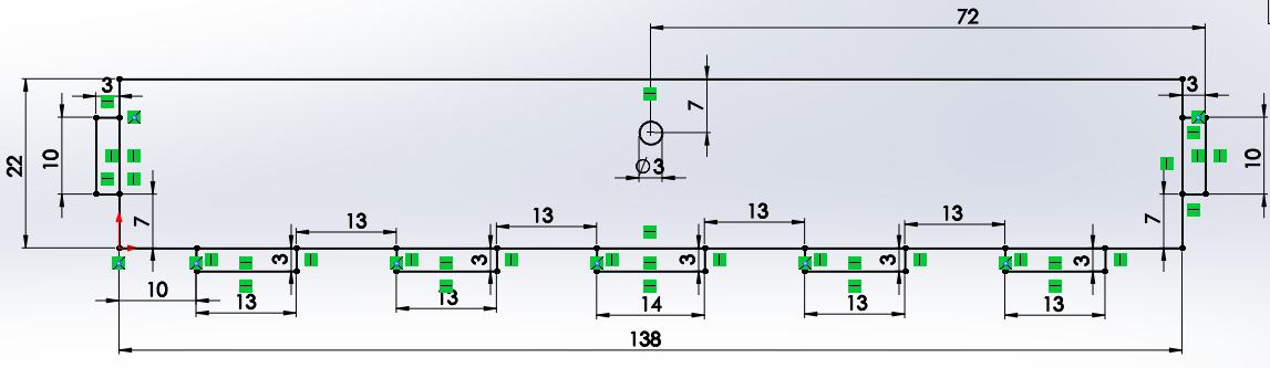
- Repeat this process for the five finger joints that need to go at the bottom of the finished shape.
- Use the circle tool to add a 3mm diameter circle in centre of the shape. This will be to help your box lock shut when its closed. It's a similar process to drawing a rectangle.
- Tip: All the dimensions you need are shown at the top of this page.
- Important: Don't continue until your model is
Fully Defined.
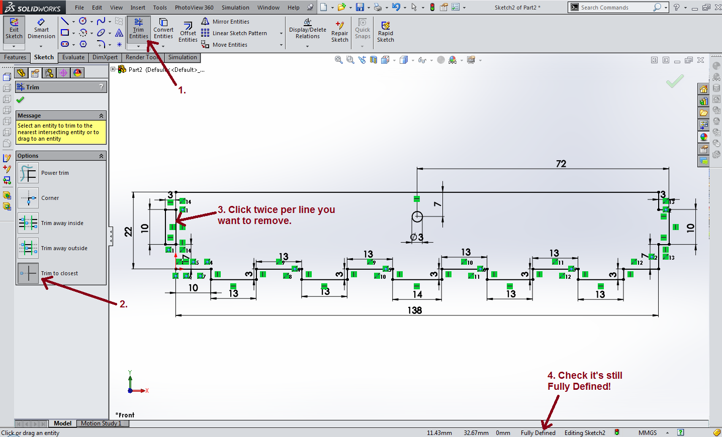
- Now, use the Trim tool like before (don't forget to turn on 'Trim to Closest') to take out the unwanted parts of your model.
- You'll need to click twice on each line you want to remove. The first click removes the line created by drawing the smaller rectangle. The second click removes the piece of the very first rectangle you drew at the begininng of this process.
- Trim away all the unwanted parts until you get something looking like the image below:
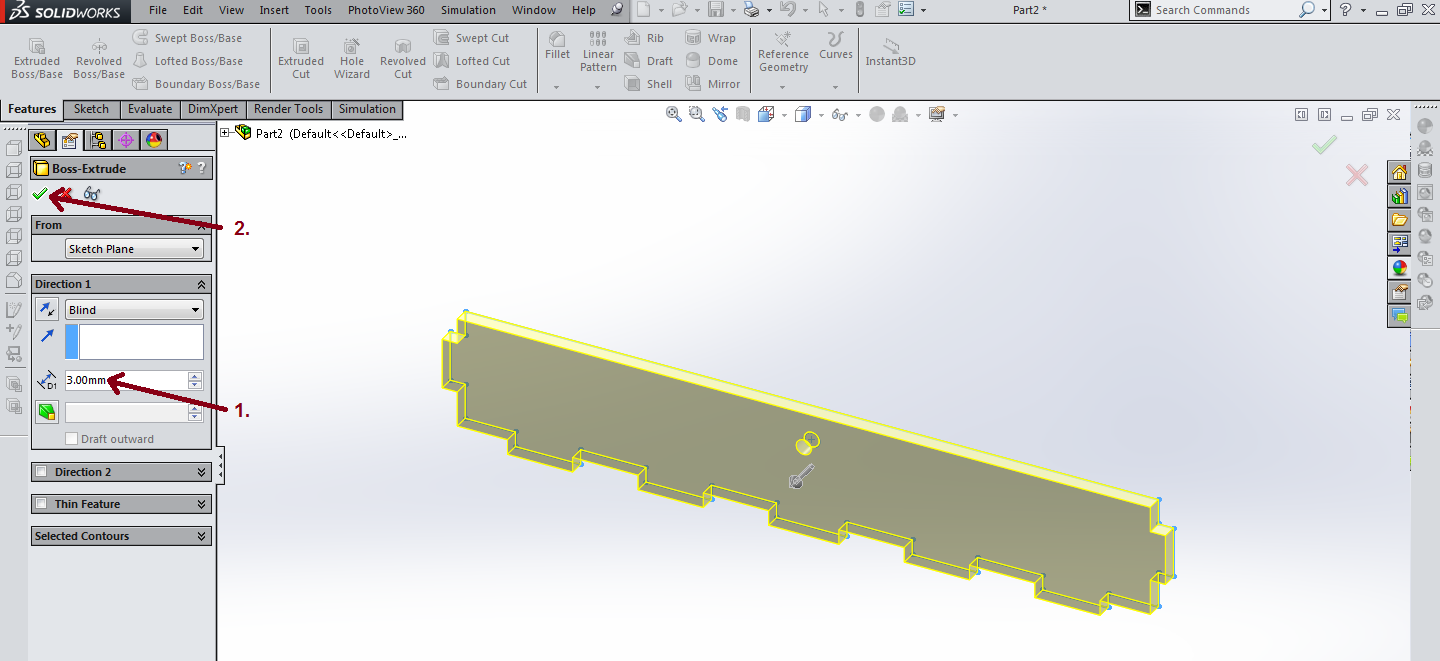
- Click 'Exit Sketch' in the top-left hand corner of the screen.
- Enter a depth of 3mm in the box to the left.
- Click the green tick in the context menu to finish your part.
Here is a video of the whole process to help:
Save It
- Save your work as lidFront
- Upload this part to the silver badge task.
2 Creating a sketch from a design
3D Designer
- Complete the task below.
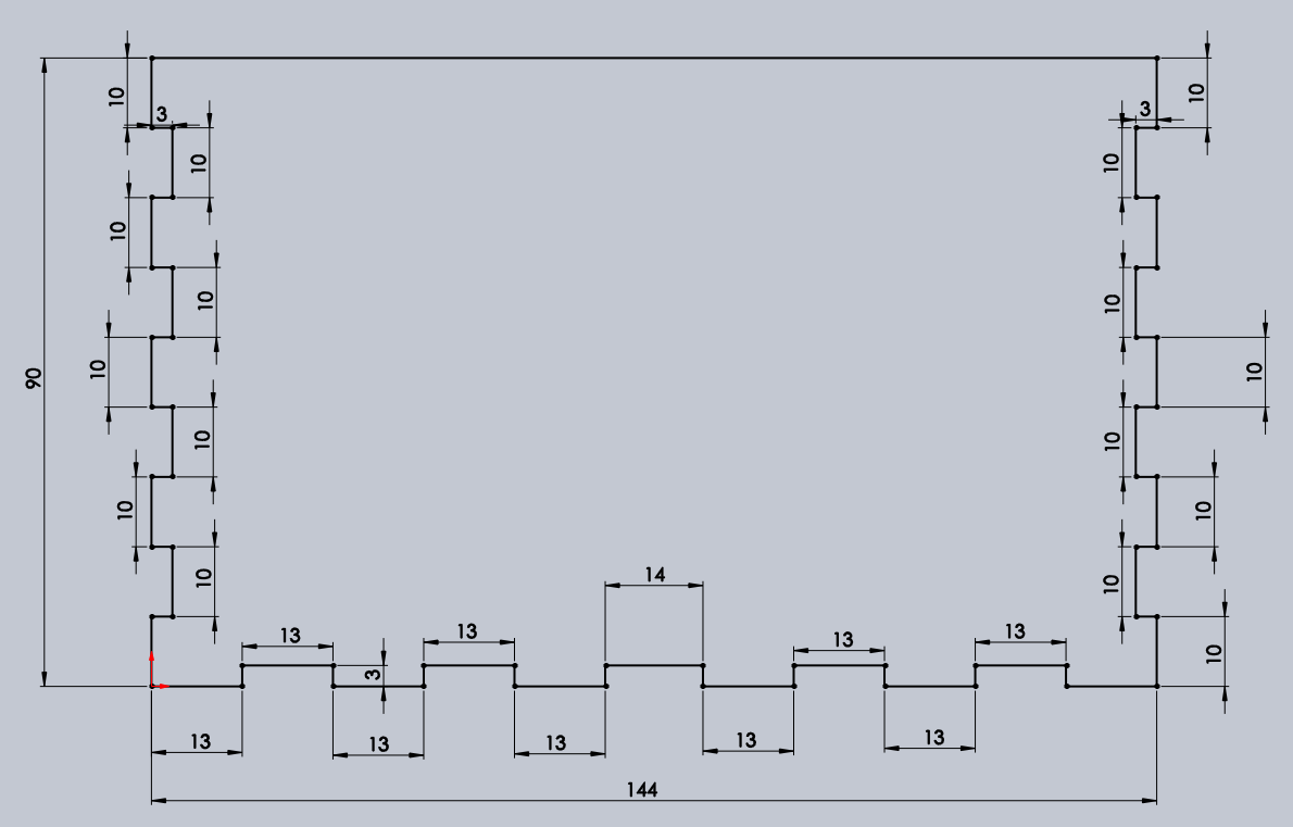
- Look at the sketch below.
- You need to draw, trim and fully define this sketch.
- Once you have completed that, extrude it by 3mm
- Take a screen shot of the full defined sketch and the 3d part for your portfolio.
- Once complete, save this as the Lid
- Upload this completed task to the Gold badge.
3 Creating a sketch from a real part
3D Designer part 2
- Complete the task below
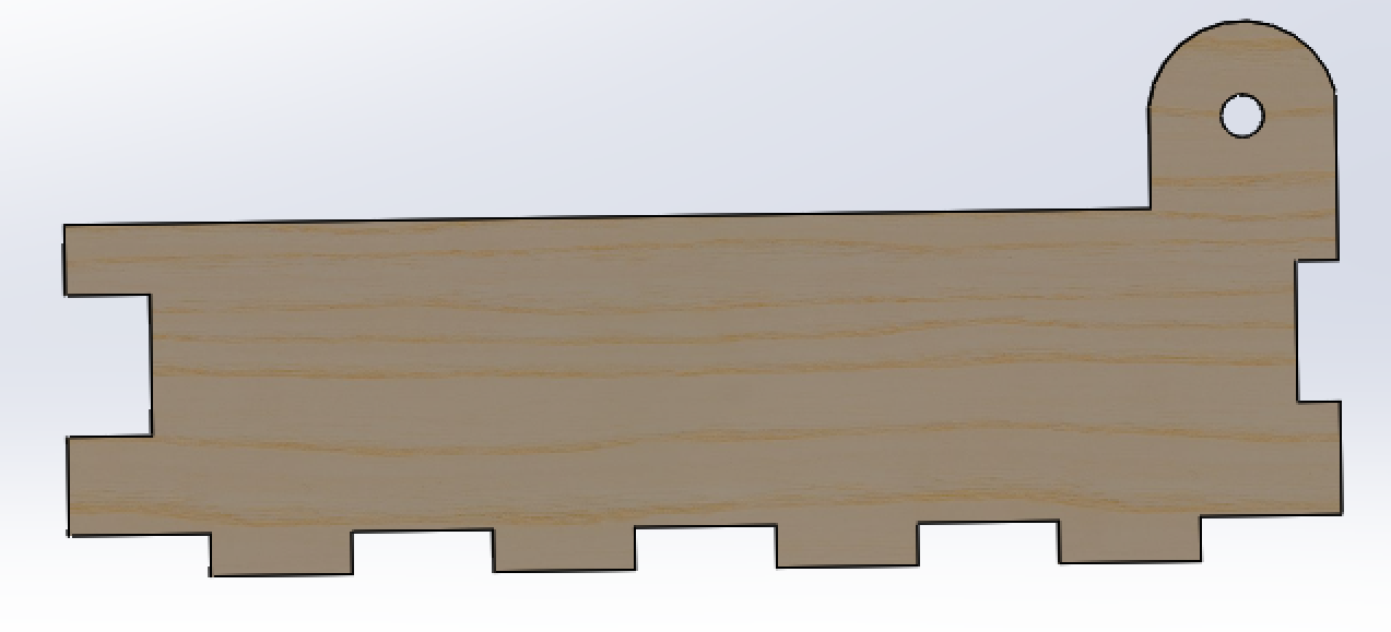
- Find the part that looks like the image below. It's the base of the box.
- Use a pair of calipers to measure the dimensions of the part carefully.
- Watch this video to see how to use a pair of verniers calipers.
- Use SolidWorks to create your own sketch of the part and take a screenshot of it for your portfolio.
- Extrude the sketch to produce a 3D part and capture a screenshot for your portfolio.
- Save the completed file as baseSide
- Once complete, upload this part to the Platinum badge.