The 555 Fan
1 Using a potentiometer
Learn It
- A potentiometer is a component we can use in our circuits as potential divider.
- Before you learn about the potentiometer, you need to learn what is meant by a potential divider.
Try It
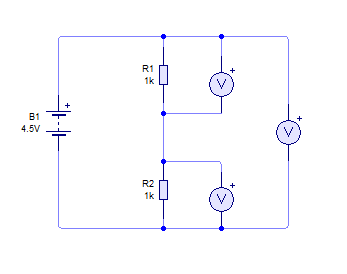
- Open Circuit Wizard and create the circuit shown below.
- When opening Circuit Wizard, you will always select the 'Circuit with GENIE flowchart' option.
- The symbol with an V in it is an Voltmeter - which will be found under 'Test instruments' at the bottom of the options list.
- Now press play and the three voltmeters should show potential difference across each of the resistors and across the pair of them.
- Because both resistors have the same value, the potential difference supplies by the battery is equally divided across each resistor.
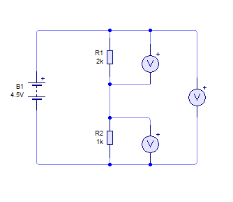
- Now let's change the value of one of the resistors.
- Press play again, and see how the potential differences have changed.
Badge It - Silver
- Complete the table below by changing the values in your circuit diagram.
- Take a screenshot of each of your circuit results to upload to www.bournetolearn.com
- Note - 500mV is = to 0.5V

- Can you see a pattern between resistor values and potential difference?
- Click on this link to complete the quiz which will badge your work.
- You will also need to upload you screenshots of the circuits.
Learn It
- If we know the resistor values and the total potential difference provided by the battery, it is easy to work out what the potential differences across each resistor will be.

- If we want to find Vtop then we can just do the following

Try It
- Why is this important?
- By changing resistor values we can influence the timing of the 555 timer chip. This will speed up or slow down the time the capacitor takes to charge.
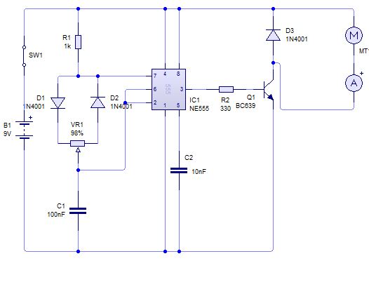
- Set up the circuit as shown below.
- Note, you will find the NE555 timer in the 'Integrated circuits' option in Circuit Wizard.
- SW1 is a switch - which will be found under 'Switches', IT IS THE FIRST 'LATCHING SWITCH' OPTION. Third one down - SPST.
- C1 and C2 are capacitors - which will be found under 'Capacitors'
- D1 and D2 are diodes - which will be found under 'Diodes'
- Q1 is a transistor - which will be found under 'Transistors' > NPN Transistors
- The symbol with an A in it is an Ammeter - which will be found under 'Test instruments' at the bottom of the options list.
- VR1 is the potentiometer - which will be found under 'Resistors' - you will need to change it to 10k (the default is 100k).
- MT is a motor - which will be found under 'Electromechanical'
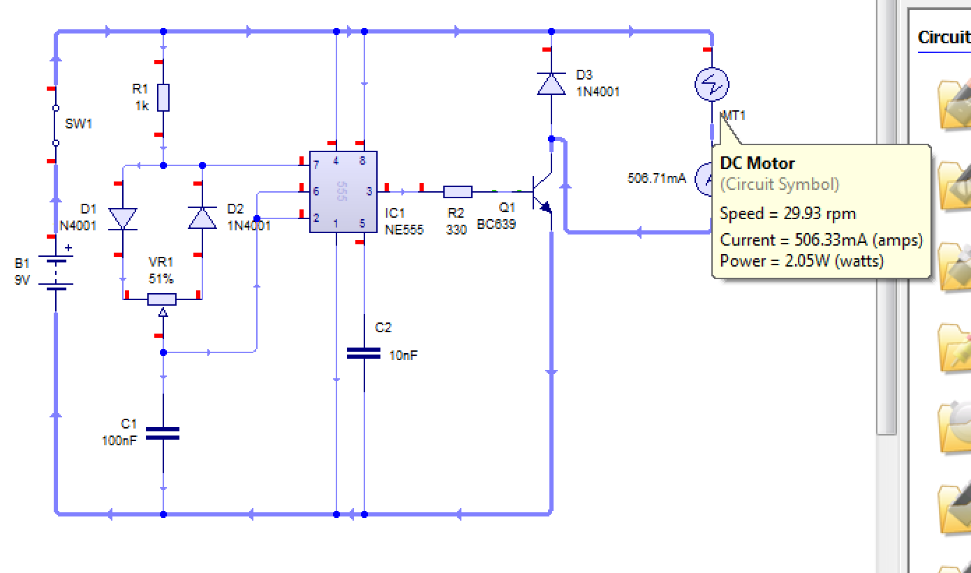
- Simulate the circuit and then start adjusting the potentiometer.
- If you hover the arrow over the motor, you can see the rpm of the motor and the current flow.
- Change the value of the potentiometer and see how it affects the speed and current flow through the motor.
Badge It - Gold
- Draw a graph to display how changing the value of the potentiometer changes the speed of the motor.
- To learn more about the operation of the 555 timer, watch the video below:
Learn It
- It would be inconvenient to have to swap in and out resistors to alter the potential difference reaching our 555 chip. This is where a potentiometer comes in handy.
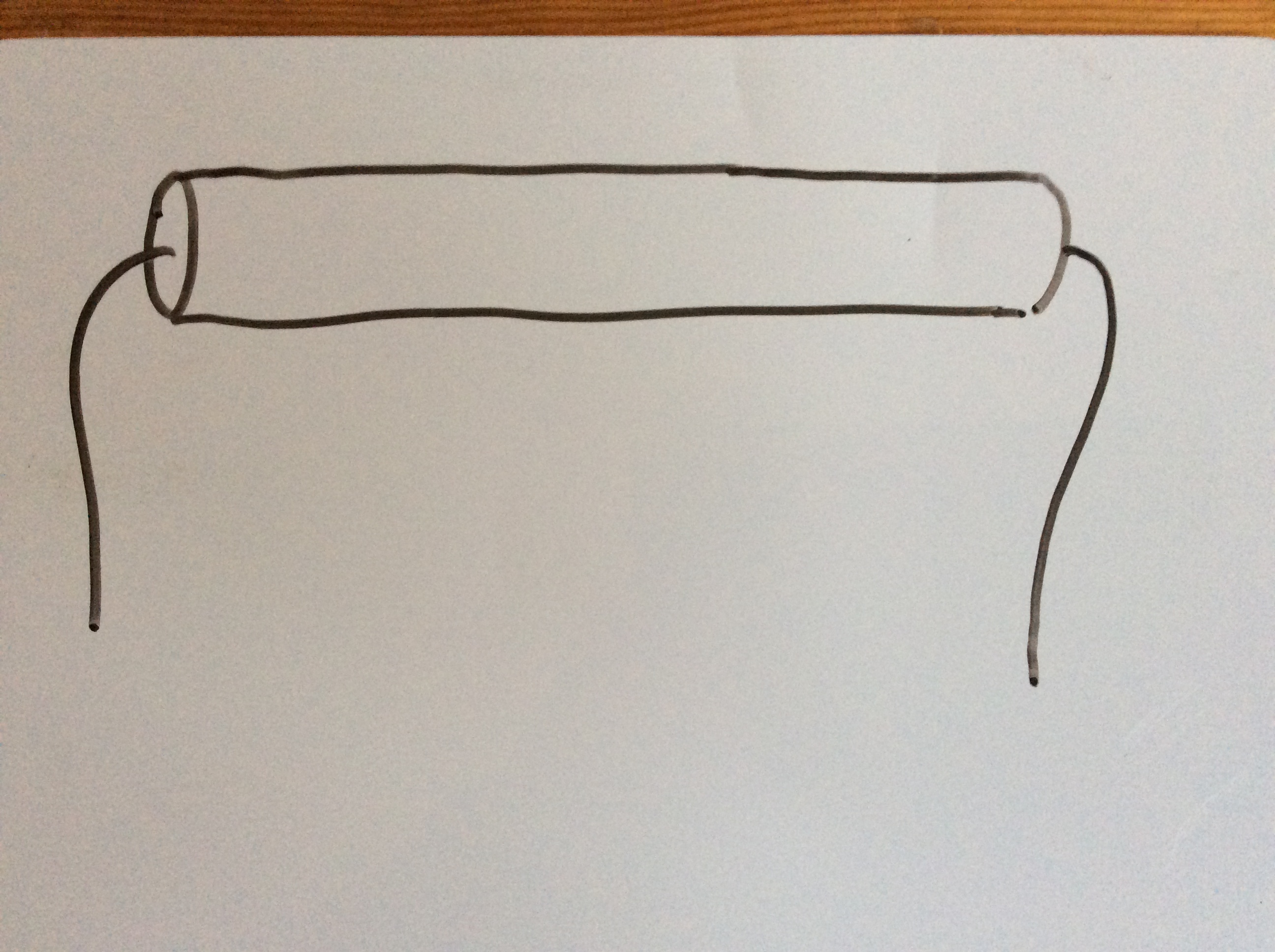
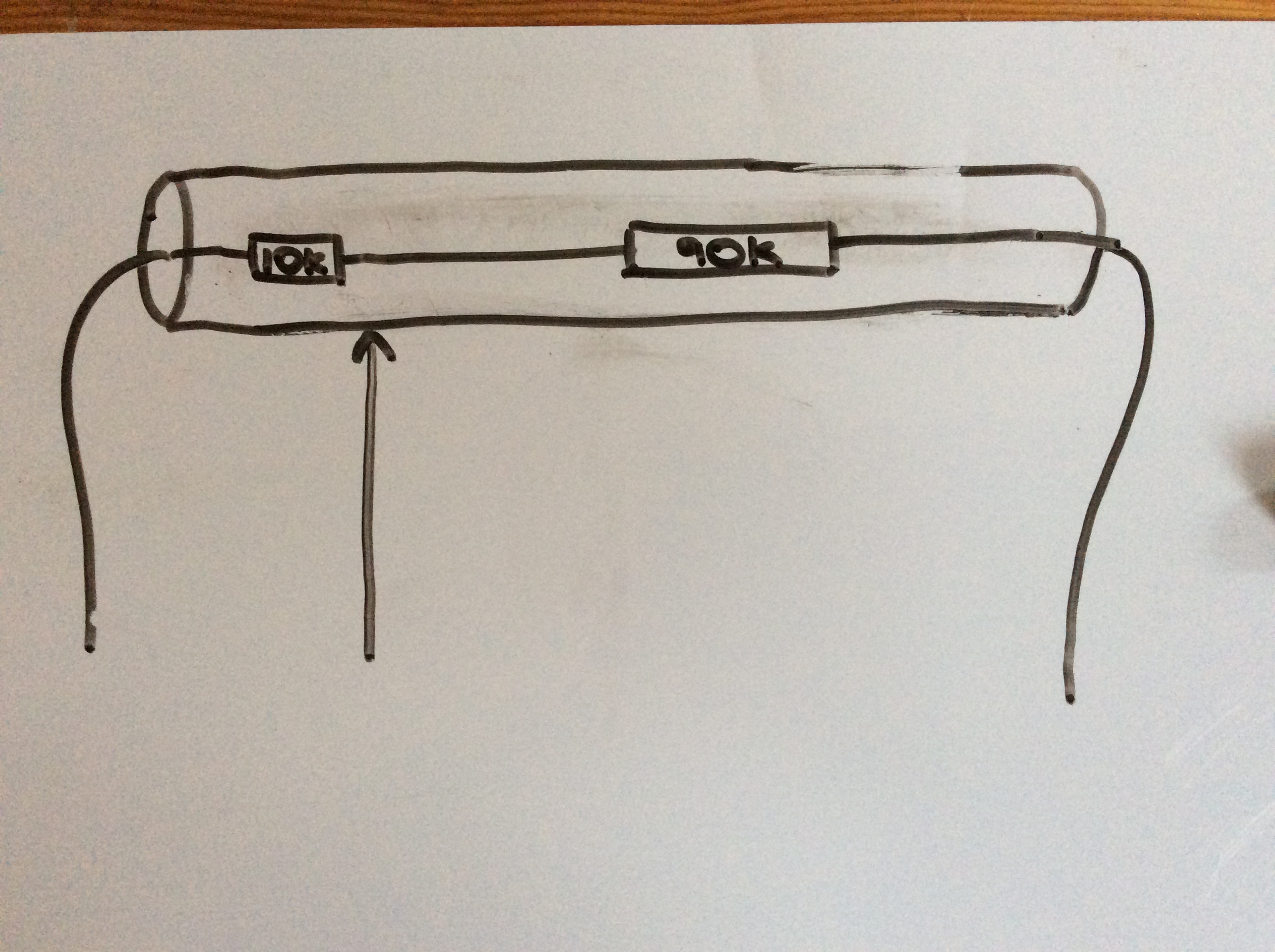
- Imagine you had a length of resistive wire - as shown below.
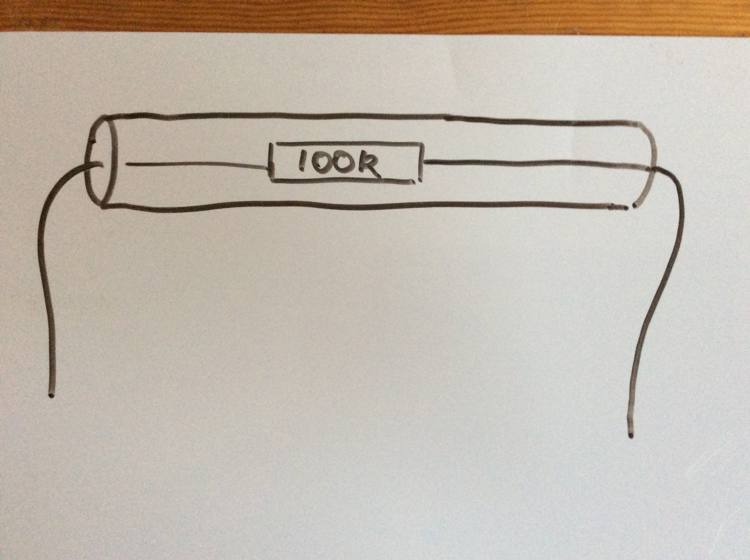
- We can consider this wire to be the equivalent of a single resistor.
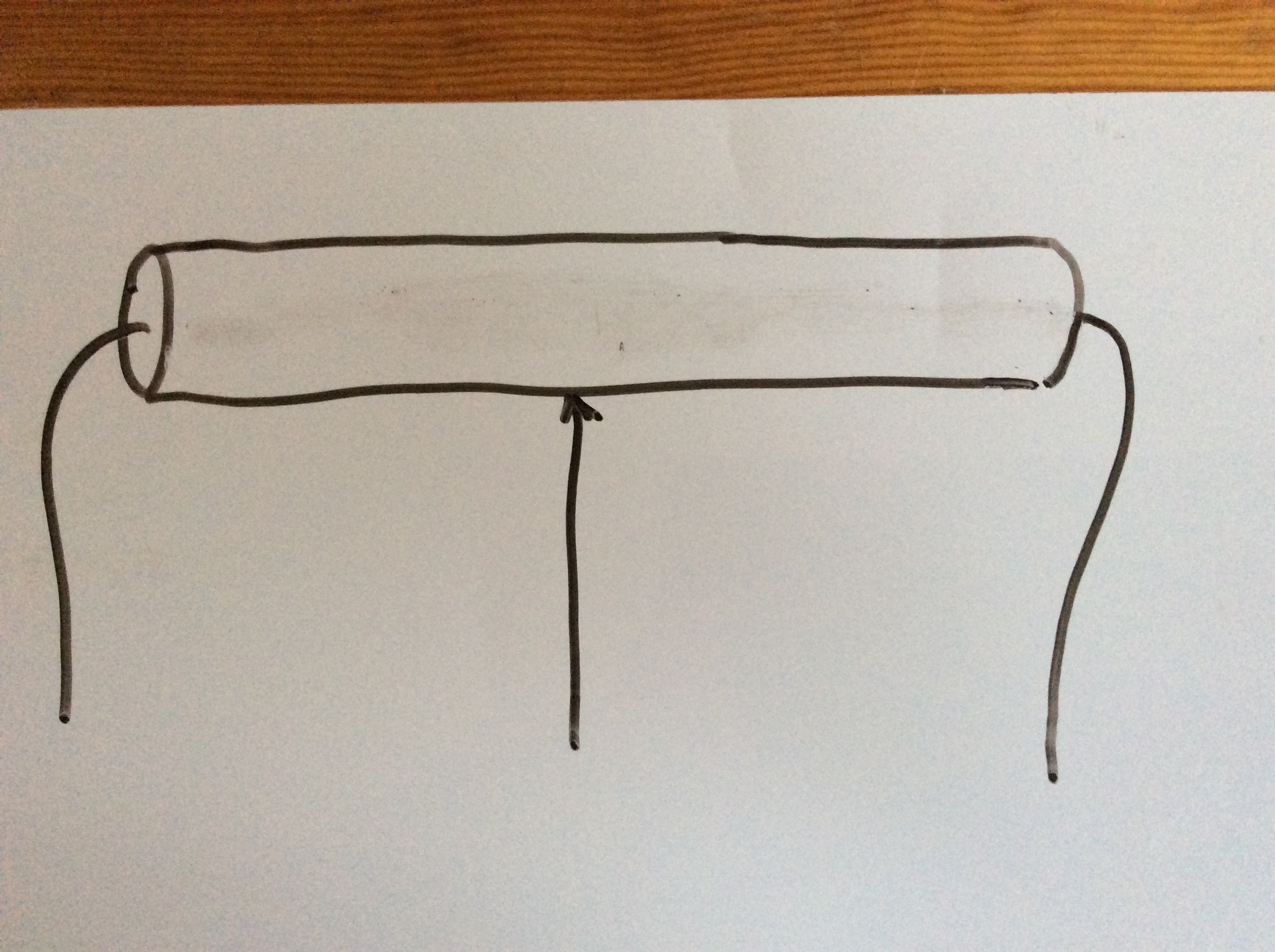
- But we can place a third contact point midway along the wire. This now divides it up into two resistors.
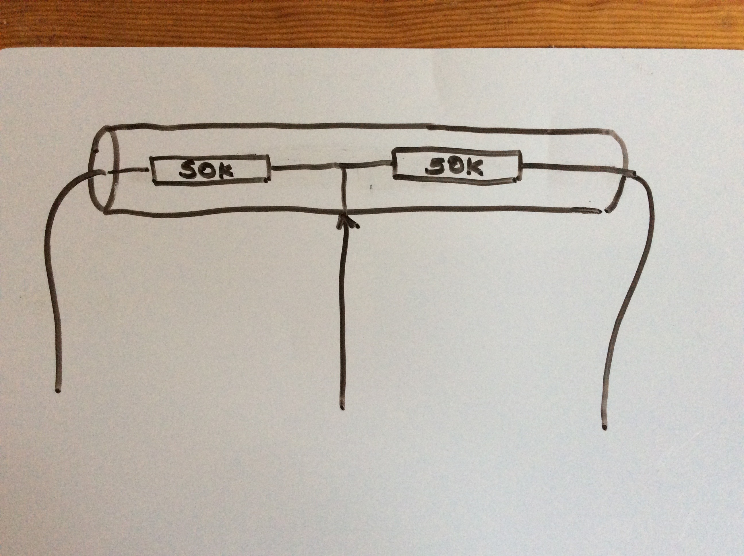
- This then makes it the equivalent to two resistors.
- Now we can vary the size of the two resistors by moving the third contact point up and down the wire.
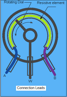
- This is how a potentiometer works. A coil of wire is used and the third contact point is normally moved by rotating a dial.
Build It
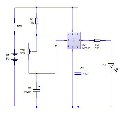
- Let's place a potentiometer into a circuit.
- Simulate the circuit and adjust the potentiometer to see how it effects the LED.
Badge It - Platinum
- Adjust the values C1 and VR1 and write up an explanation as to how the potentiometer and the capacitor affect the LED output.