The 555 Fan
1 The PCB build
Learn It
- In this project you're going to build a desktop-fan, whose speed can be controlled using a component called a potentiometer.
- The circuit uses a 555 timer chip to control the fan.
- You've had plenty of experience of soldering PCBs by now, so minimal guidance has been provided. However, putting together the actual fan takes time, so you are better off starting early.
Build It
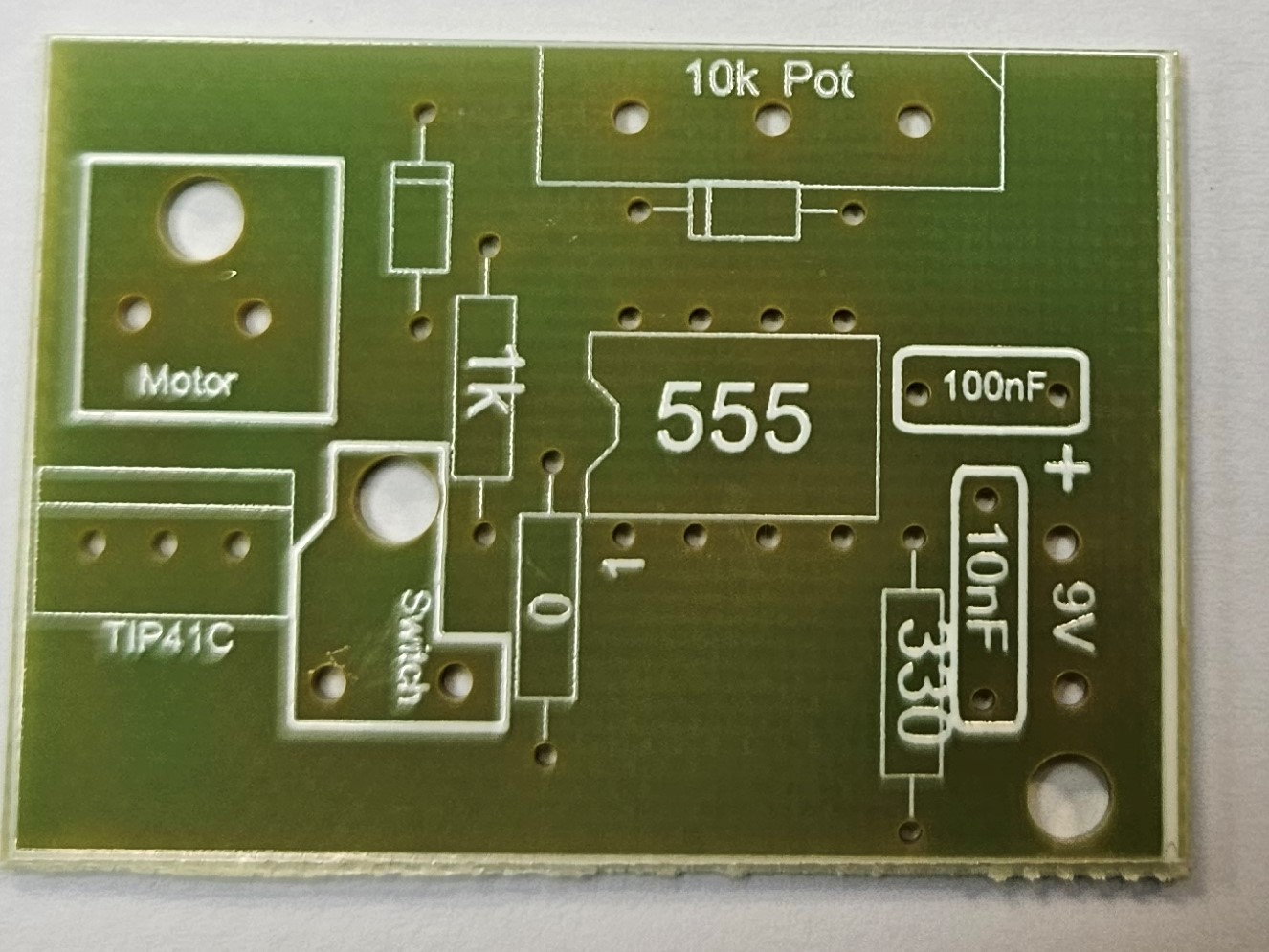
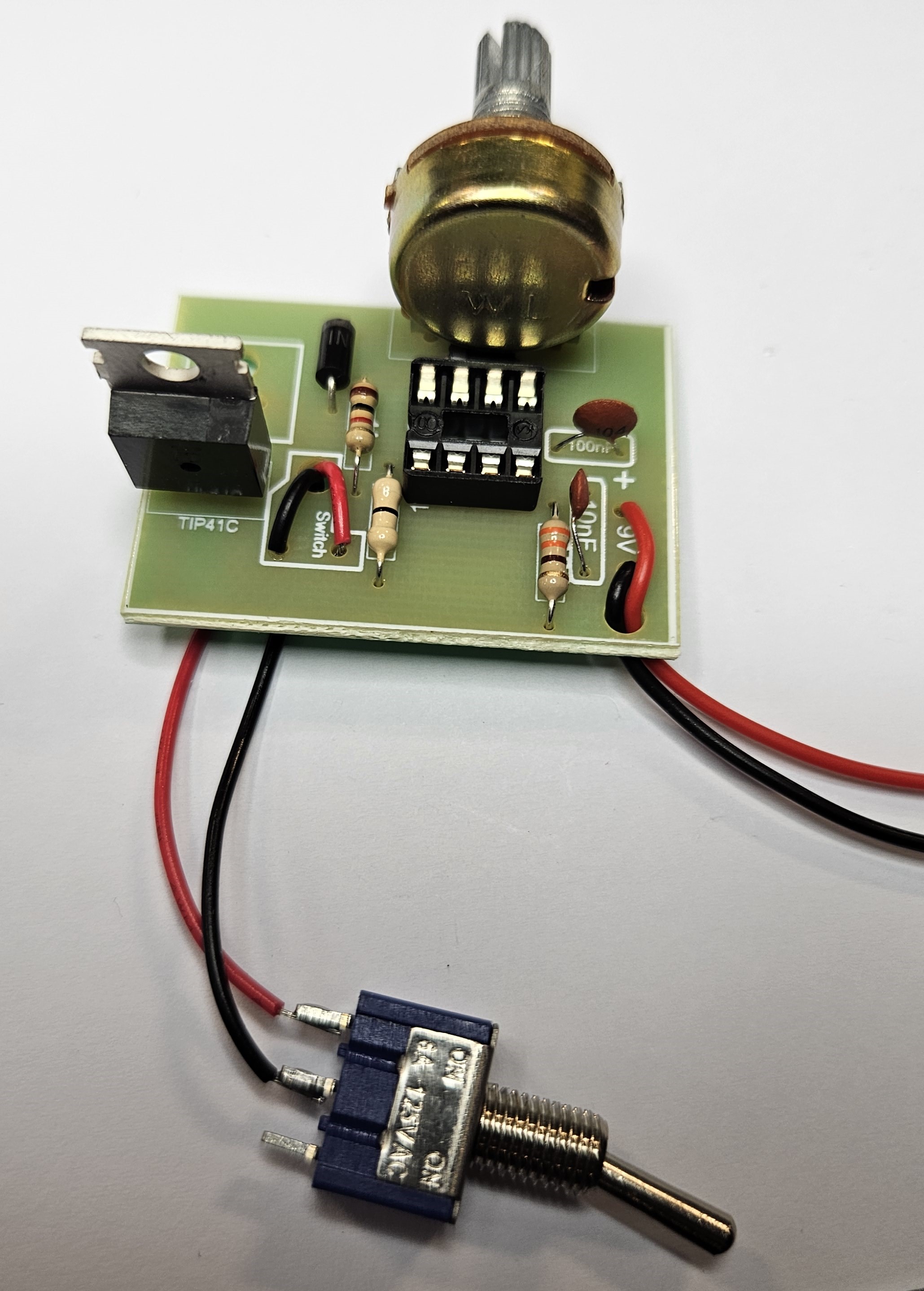
- Here is the board you will be soldering together.
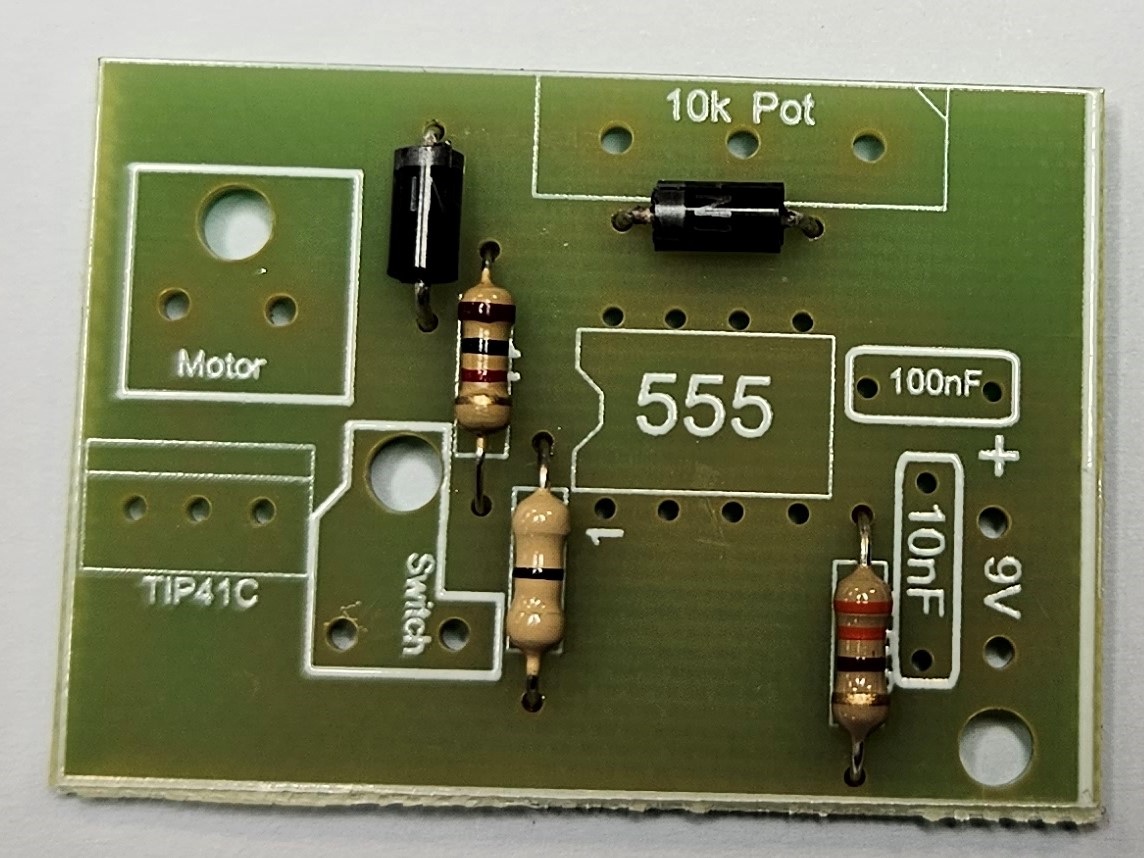
- First, you need to add the 2 rectifier Diodes. Make sure you put them the correct way around, you can also add the 3 resistors.
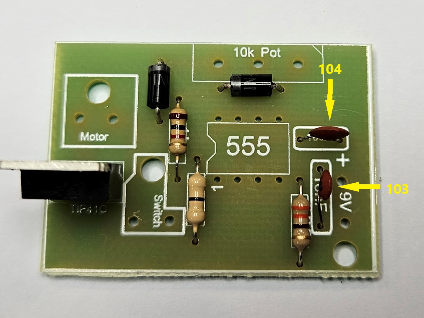
- Next add the 2 ceramic capacitors. Be careful, there are 2 values 10nF (103) and 100nF (104).
- You can also add the TIP41C transistor. Make sure this is the correct way around.
- You can now add the Potentiometer, before doing this, there is a little metal tag that needs removing, using the long nose pliers.


- Now you can solder in the Potentiometer, the 8-pin chip carrier and the battery snap.
- Don't forget to put the battery snap through the strain relief hole.


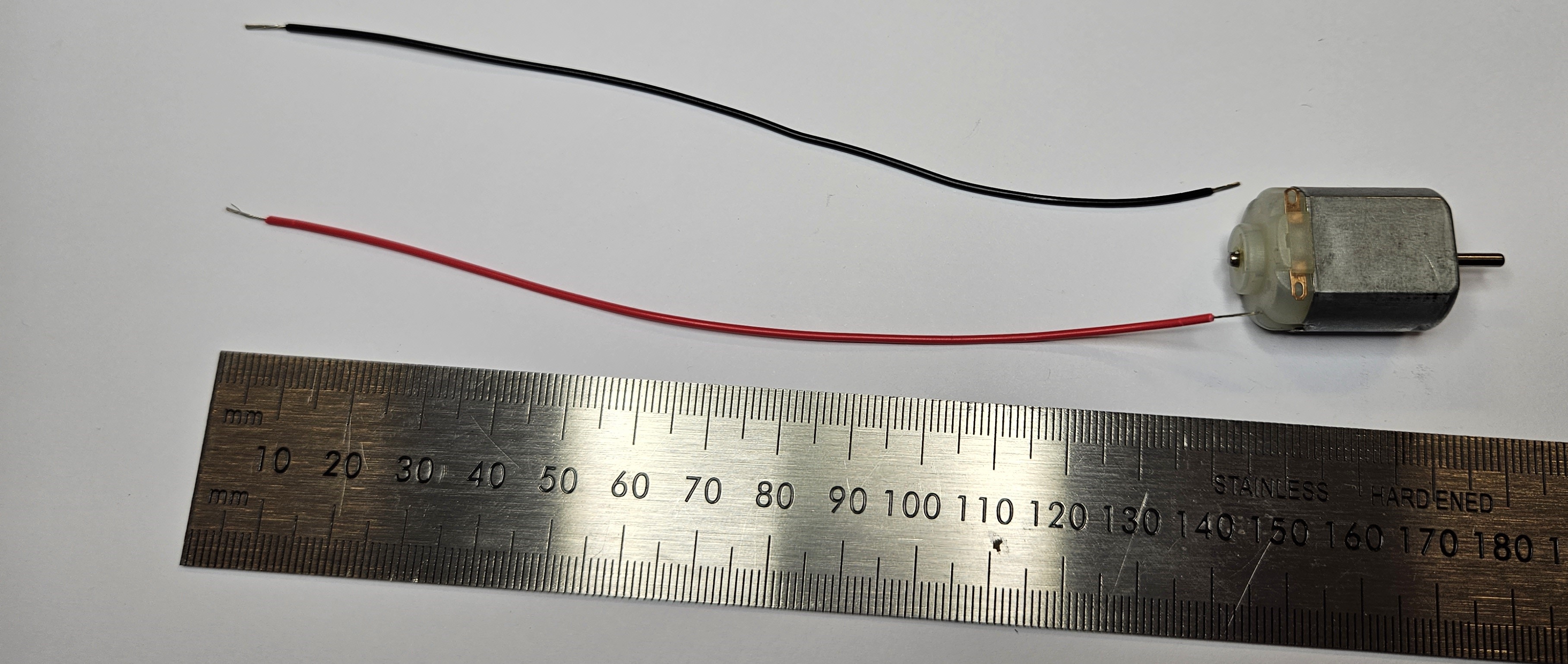
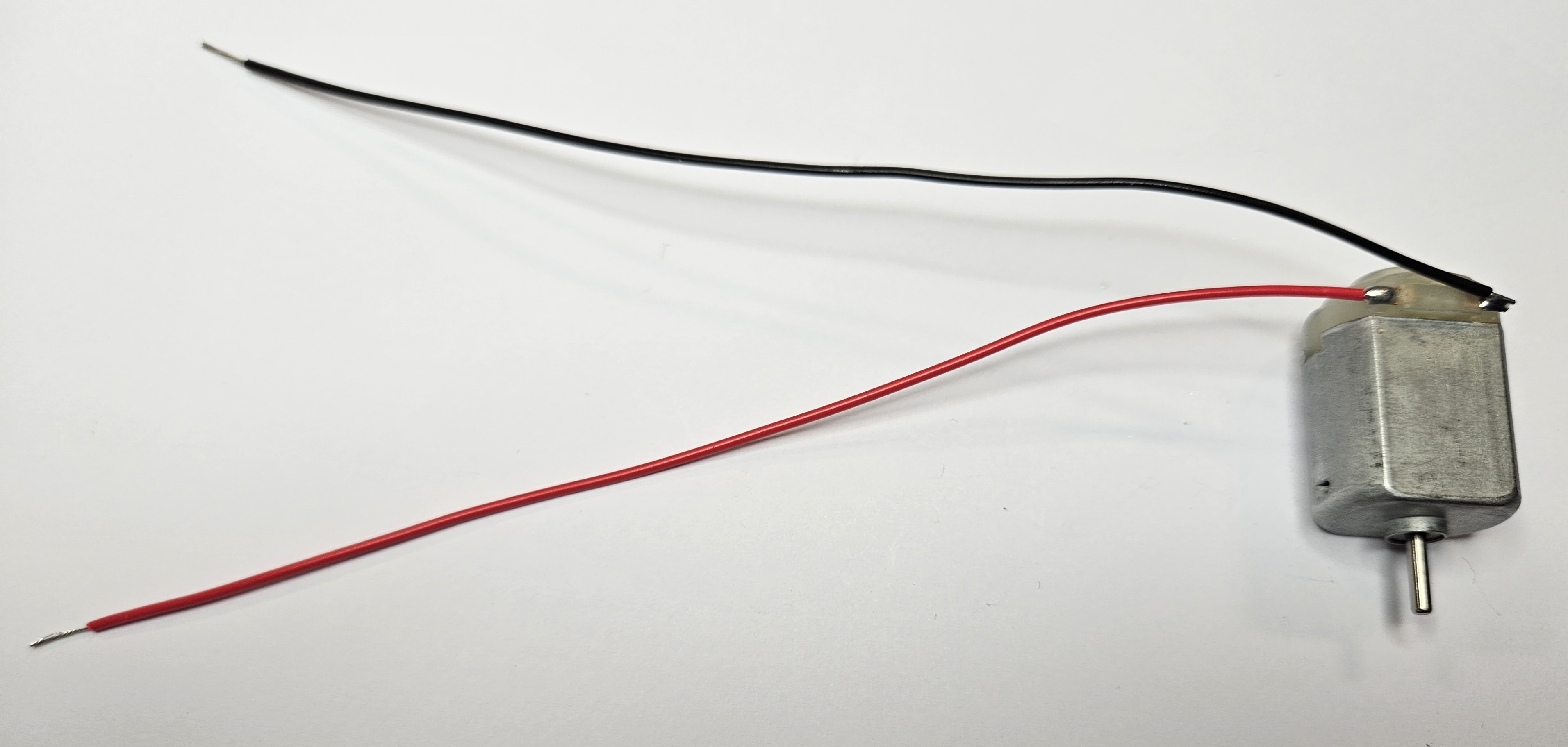
- You need to now cut 2 sets of red and black wires.
- 140mm (14cm) for the motor.
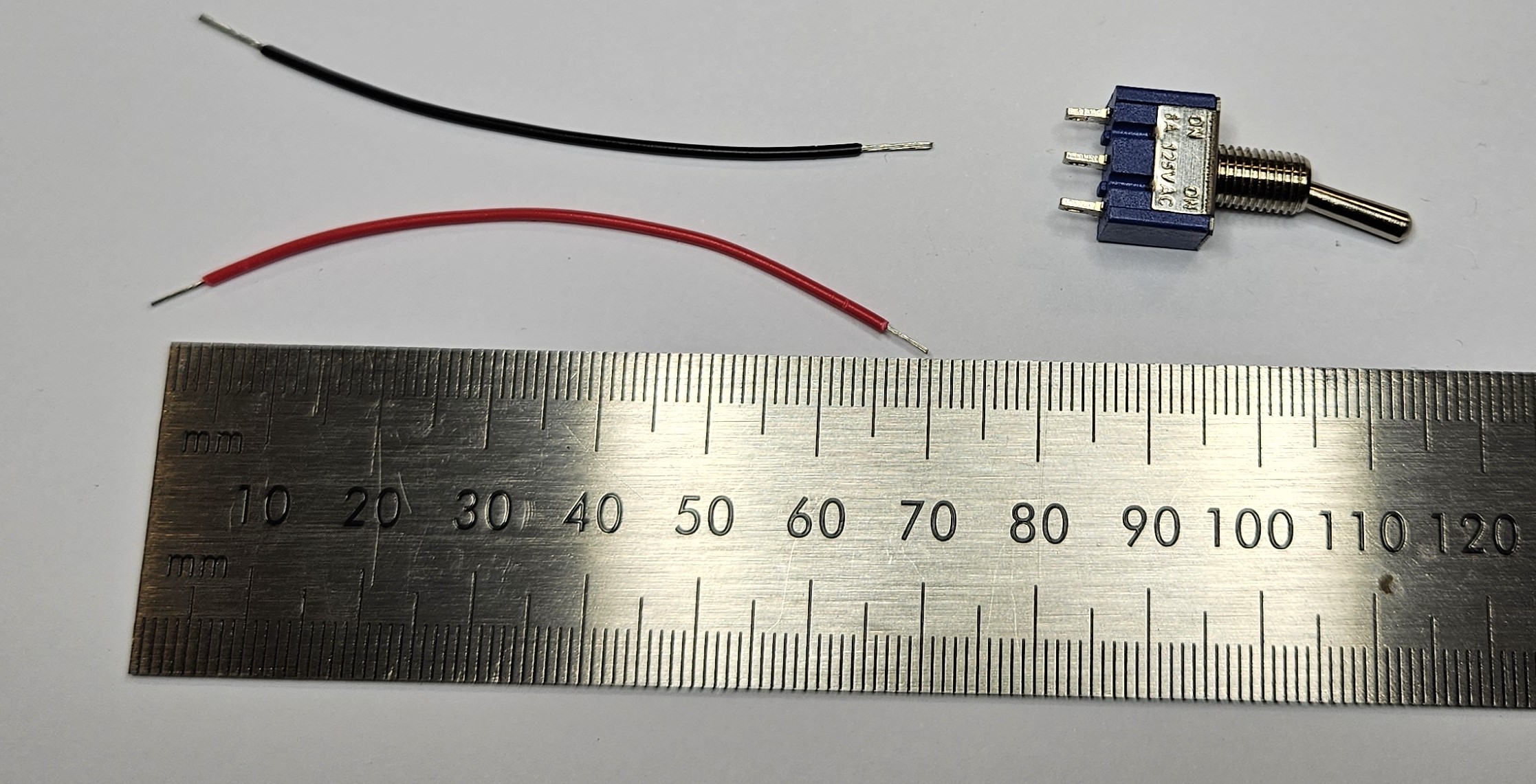
- 70mm (7cm) for the switch.
- These can now be soldered to the motor and the switch. Please note how the wires are soldered in a particular direction on the motor.
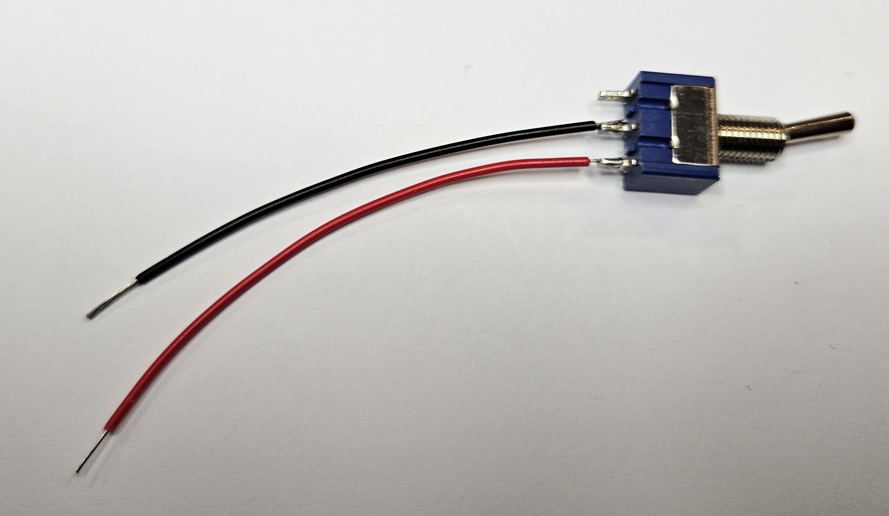
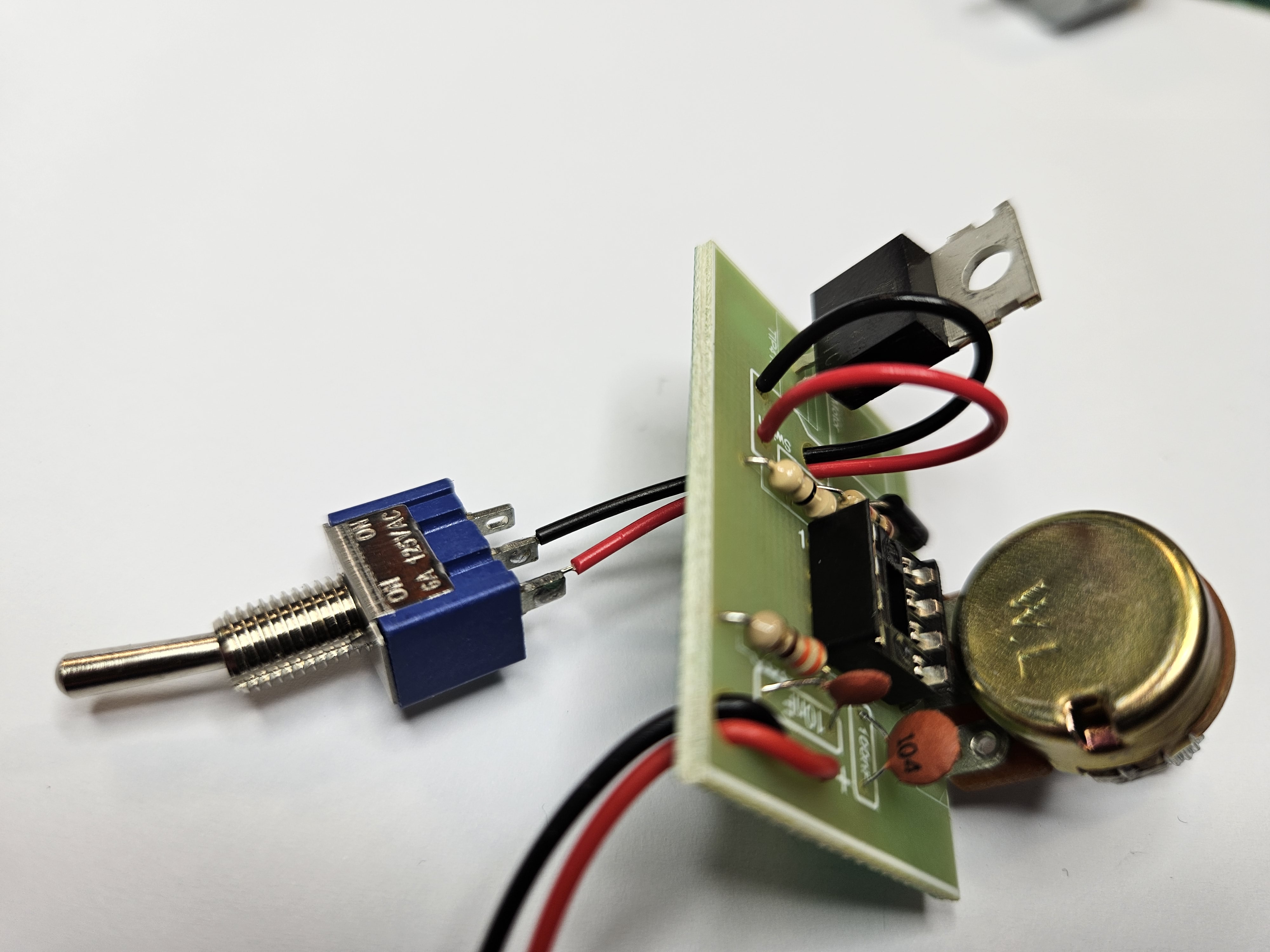
- You can now solder the switch to the PCB.
- Make sure they go through the strain relief hole.
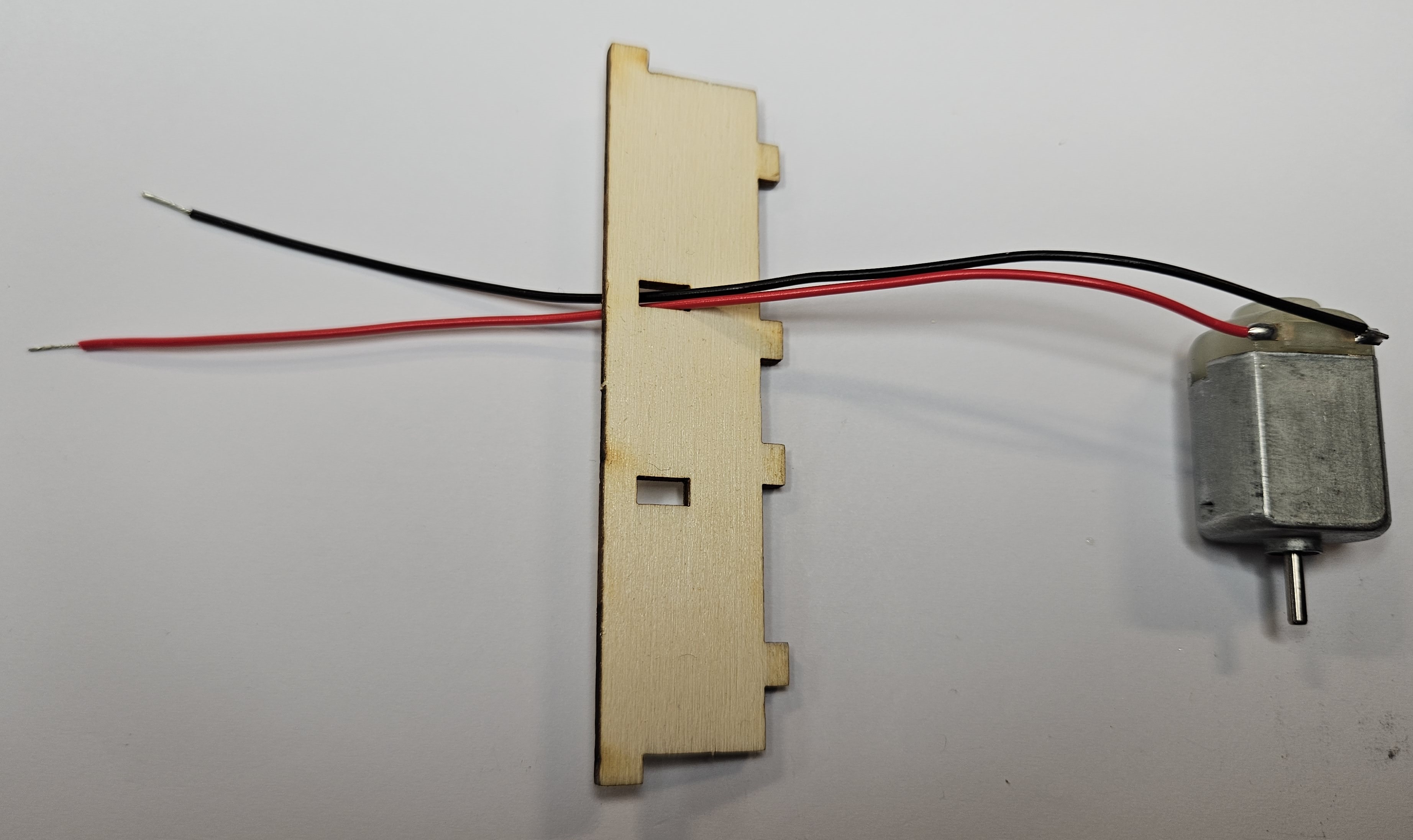
- The wires for the motor can now be fed through the housing and then soldered to the PCB.
- Also, make sure you note which colours go in which hole, or the motor will not turn in the correct direction.
- Again, make sure you use the strain relief hole.
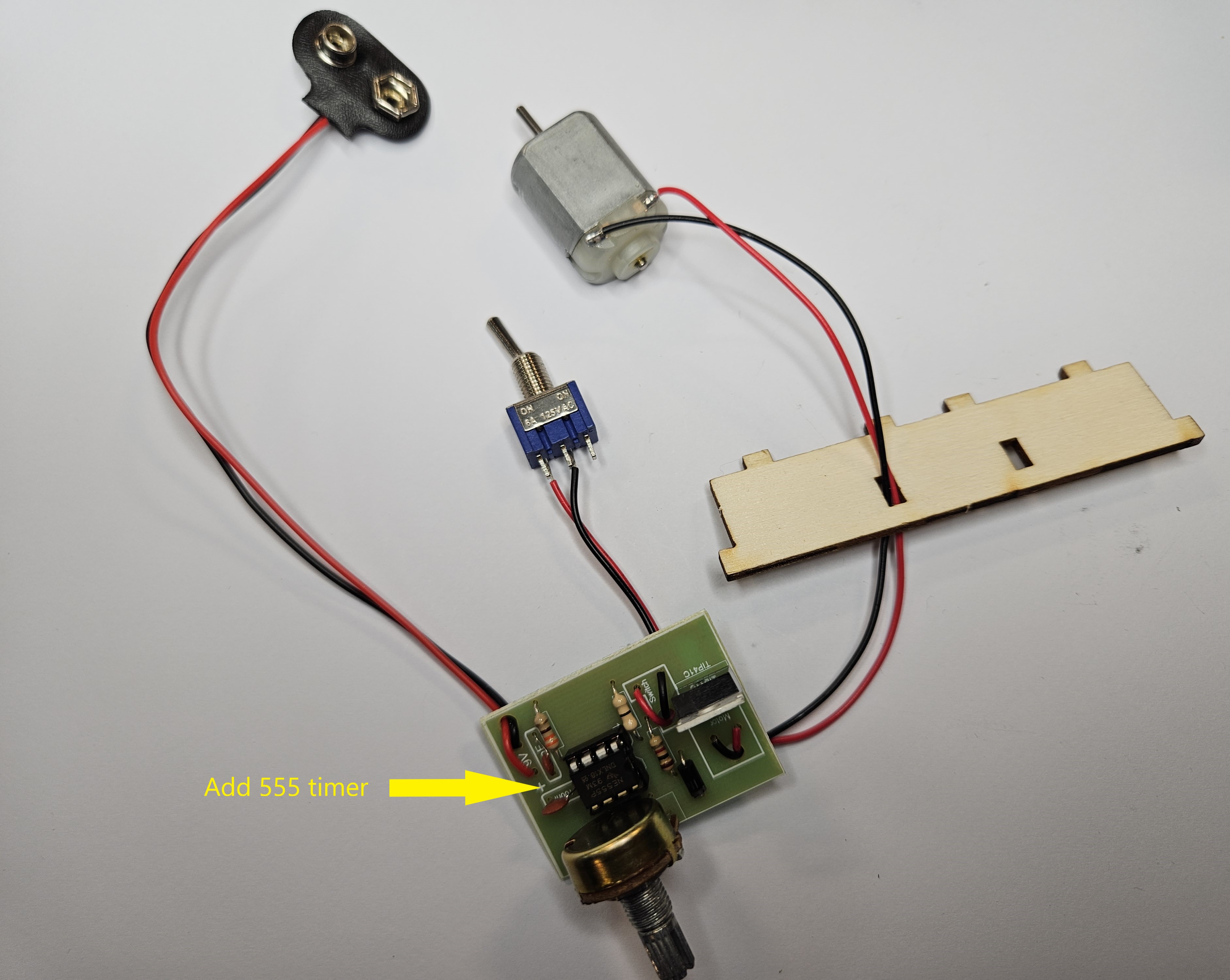
- You can now plug in the 555 timer IC and test the circuit works.
- Finally, you can choose a colour for your fan blade and fit it to the motor.
- When fitting this, ensure the back of the motor is on the desk and do not push the fan blade all the way to the motor housing, or it will not turn.


Badge It
- Take photos of the solder and component side of your board, and the leads to your switch. Your badge will be awarded according to the quality of your work.
- Now it is time to test your board.