| Challenge 1 | Challenge 2 | Evaluation | Homework Tasks | Achievements |
Stripboard Circuit Design

Contextual Challenge (the problem that needs solving)
If you were to design printed circuit boards (PCB), you would need to purchase expensive equipment and software to make them. You will research a cheaper easier way to make a fixed circuit. This will allow you to design and make projects at home using inexpensive tools and materials.
1 Stripboard Circuit Design
- Imagine you're an electronics hobbyist, and you'd like to build a circuit from parts you've got laying around. Chances are you don't want to spend £400 on an etch tank, £60 on chemicals and make a mess of your kitchen sink. Instead, one can purchase stripboard from electronics shops or online websites such as EBay or Amazon. These can be used to create compact, permanent circuits at home.
- The creatively titled stripboard is a board which has thin strips of copper running along it, with each strip containing dozens of 1mm holes. By soldering components between different columns, and using a small drill bit on a handle (known as a spot face cutter), almost any circuit can be quickly created. This requires a steady hand though, as it is easy to accidentally solder tracks together.
- Before you start the tasks, you'll need to load up the DIY layout creator. This program can be found in the open drive at Design Engineering - Student Home Software - DIYlC, or alternatively can be downloaded for home use over at the creator's homepage, here.
- Here is a video, which will help you through the following steps if you get stuck.
The design challenges
- For each of the circuit diagrams, use DIYlc to create a stripboard design, so you could make these designs in real life.
1: Using DIYlc, design a simple LED light circuit. SILVER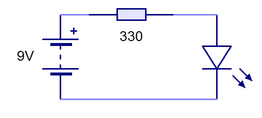 2: This time, there are 3 LEDs and resistors to connect together in parallel. To make this design more compact, you may wish to use the spot face cutter. GOLD part 1
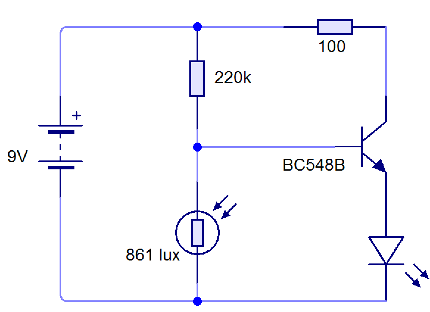
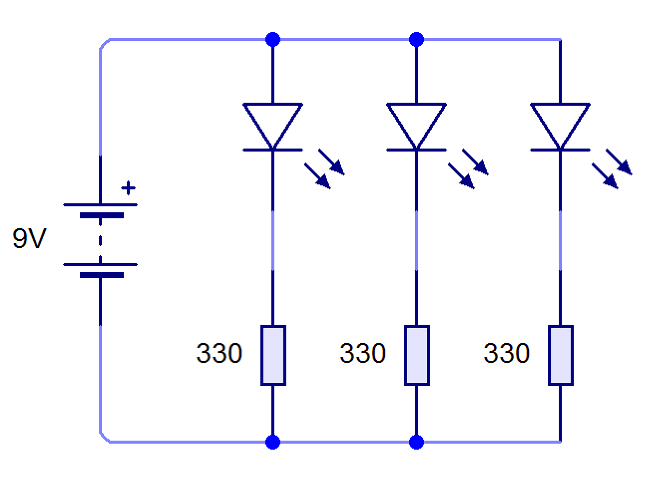 3: This circuit uses a pair of resistors set up as something known as a Potential divider. While the simulation is running, click on the LDR and adjust the light level by moving the slider. When does the LED come on? When could this circuit be useful in real life? GOLD part 2
- HINT: If you intend to solder this together, when holding a BC548B with the letters facing you, the leftmost pin is the collector and the middle is the base.
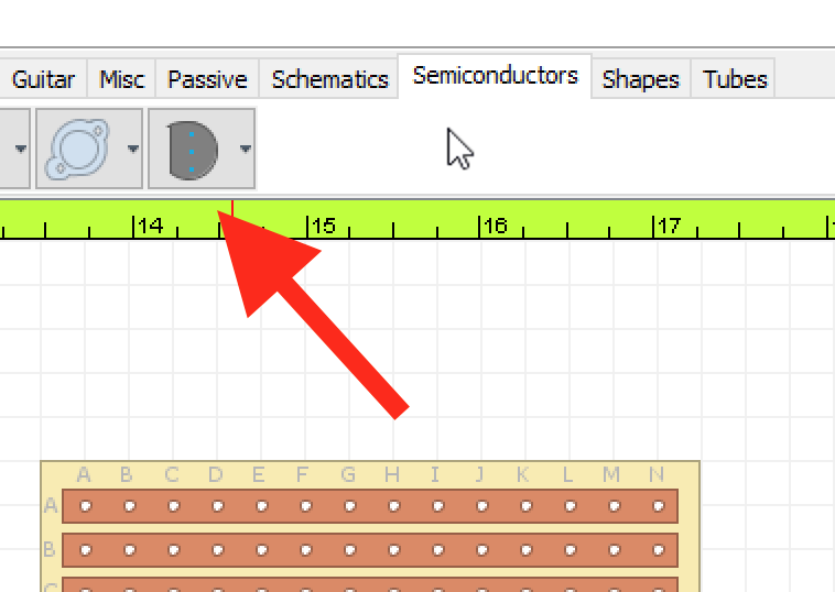
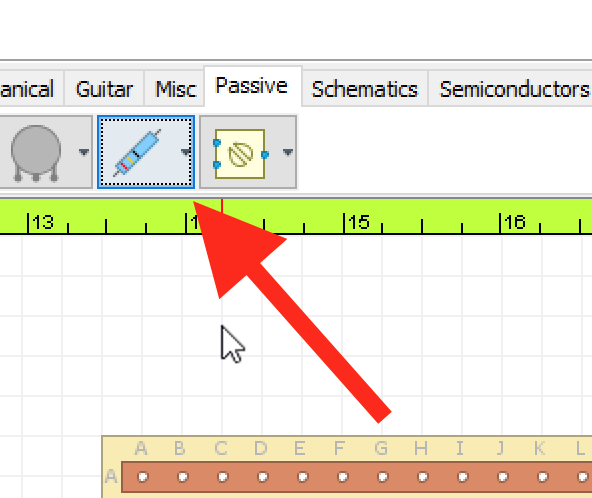
- You will find the transistor in the semi-conductor tab.
- You then need to right click on the component and go to edit selection and the change the line spacing to 0.1in.
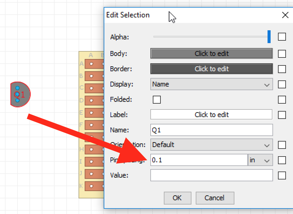
- You can now wire up the using the middle pin as the base.
- You will not find an LDR in DIYlc, you will need to substitute this with and normal resistor.
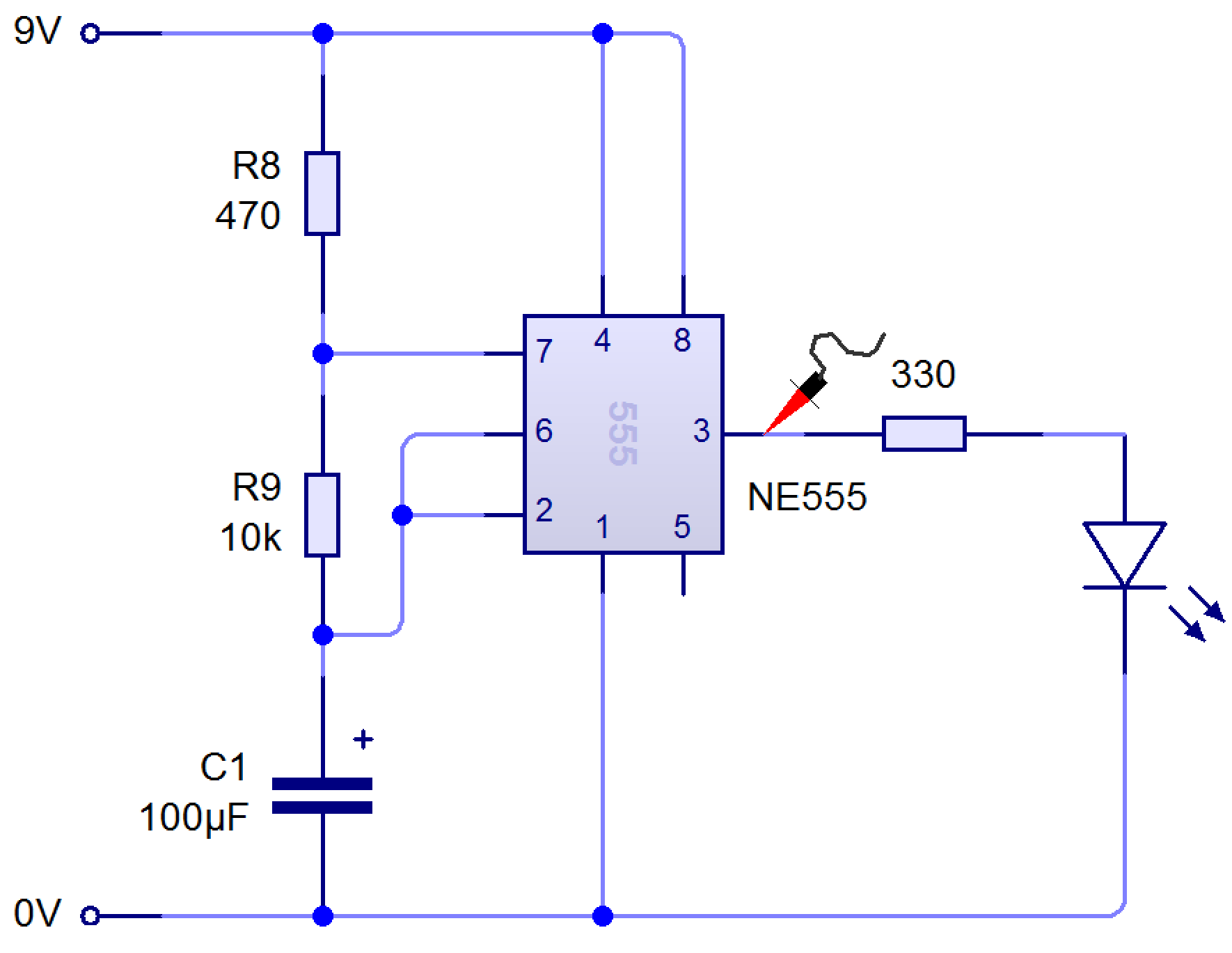
 4: 555 Timer challenge - this is a very challenging task! Aim to pack the components into the smallest possible space.
- HINT A: Remember Pin 1 in the top-left corner of the chip, and that you then count down and round in a horseshoe shape after that. Pin 8 is the top-right hand corner pin.
- HINT B: Don't forget to use a chip carrier, and not to solder your 555 timer straight to the board.
 5: Once you have completed the 555 timer design, you can build your own using stripboard. You can find the instructions for this by clicking here .
Badge It Silver
- Using the 'Snipping Tool', take a picture of your first completed DIYlc circuit in step 1.
Badge It Gold
- Upload 'snipped' pictures of steps 2 and 3.
Badge It Platinum
- Complete the 555 timer challenge and upload the 'snipped' picture of your complete stripboard.