| Challenge 1 | Challenge 2 | Challenge 3 | Evaluation | Homework Tasks | Achievements |
Fault finding challenge
Contextual Challenge (the problem that needs solving)
You will now start to design and make microcontroller circuits. When making these, there are a number of faults you will come across that will prevent the circuit from working. You will need to research these common faults in order to prevent making them yourselves.
Specification (criteria needed to solve the problem)
| Must | Should | Could |
|
Be able to identify and know where to place the following components on a PCB: LED, Diode, voltage regulator, 8-pin chip carrier, thermistor and potentiometer |
Be able to compare colour codes with measured resistor values. | Measure resistance on a variety of different components. |
| Be able to read the resistor colour code | Be able to determine if a resistor is within the tolerance limits when measured with a multi-meter. | Measure resistance on a group of resistors. |
|
Use a multi-meter to measure resistance |
Be able to measure variable resistors using a multi-meter | |
|
Identify good and bad solder joints |
1 Board fault finding and multi-meter testing
- Over the past year, you learned about electronics by making different projects that have been supplied to you. In this unit, you'll be equipped with diagnostic skills to further improve your ability to fix problems with circuits when they occur, to create and upload original programs to circuits and to create circuits without having to use the chemical etch tank.
- If you want some additional help, try reading through this short guide to using a multi-meter.
Identifying the Components
- Firstly, lets identify the components and which way around the should go.
- The 78L05 voltage regulator.


- On the PCB.

- The Diode.

- On the PCB.

- The 8-Pin carrier.

- On the PCB.

- The LEDs.

- On the PCB.

- Short Circuits - where 2 or more solder joints are connected that are not meant to be connected.

- Dry joints - Where the solder has not completed the joint or has broken away from the joint.

- Lifted tracks - where the heat from the soldering iron damaged the track and pad which has then lifted off the board.

- Take you time to get familiar with these components before you start to identify them and fault find.
The Board Faults
- There are 7 different circuit boards labelled A - G below with faults on them. There is also a component box with 3 different components to test and 4 different resistors to test, labelled A,B,C, 1, 2, 3 and 4. Inside the box are components, soldered to Machine screws (bolts with screwdriver heads). You will need to use the different settings on the multimeter as well as your ingenuity and knowledge of electronics to test the contents of each.
- The PCB's have a number of faults on them, here is a list of the possible faults you will find:
- Voltage regulator is the wrong way around.
- There is a dry joint (the solder does not go all the way around the component).
- A track has been lifted off the board.
- The 8-pin Chip carrier is the wrong way around.
- There is a short circuit (components that are not supposed to be joined are connected).
- There is an LED the wrong way around.
- Diode is the wrong way around.
- Open a .txt (NotePad) or .doc (Word) file and record which board has which fault.
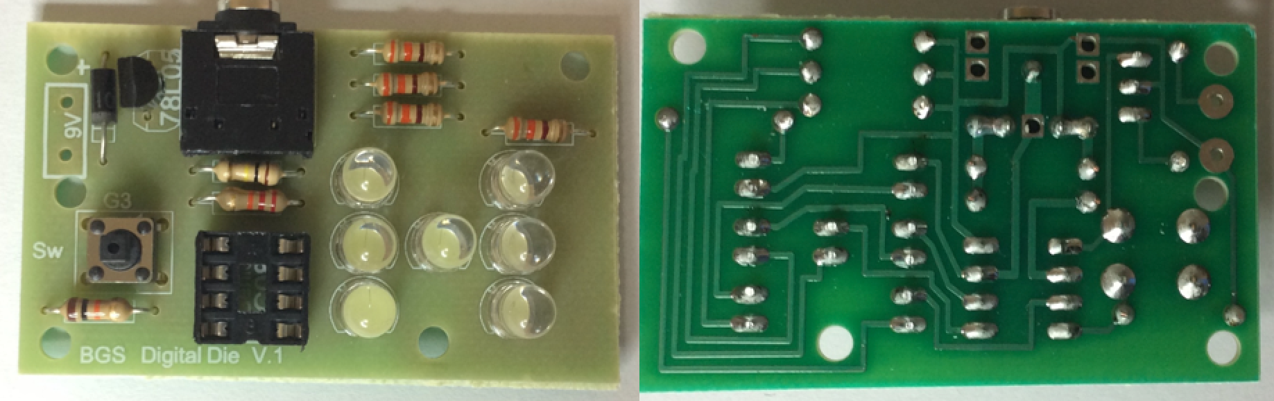
- Below is a picture of the blank PCB

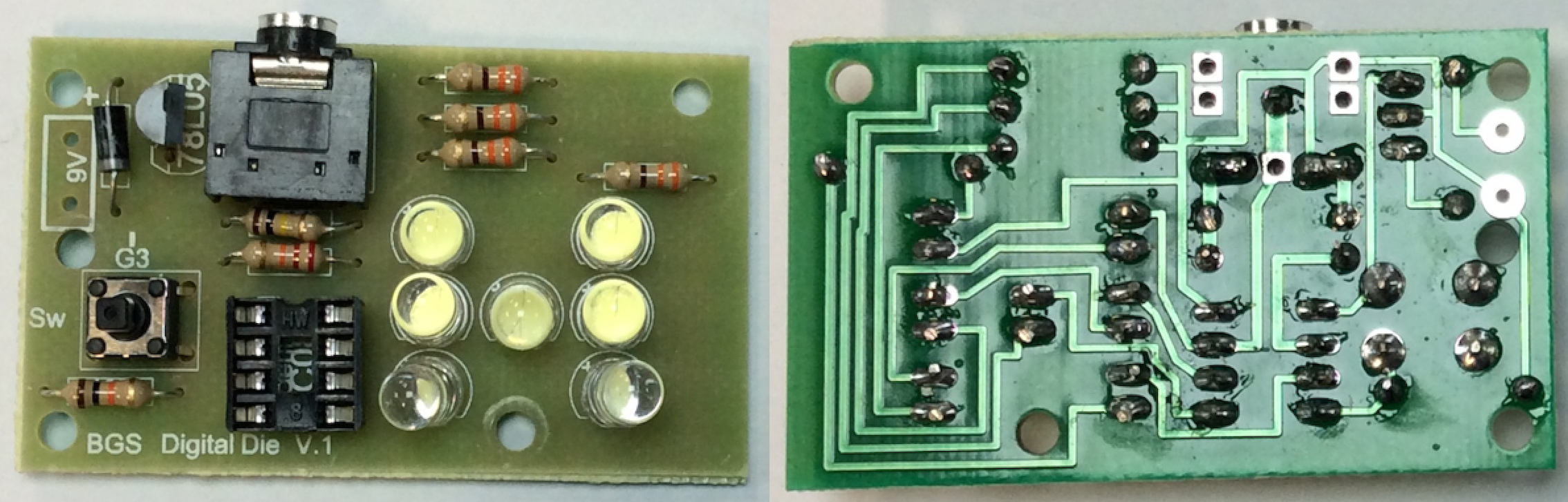
- Board A
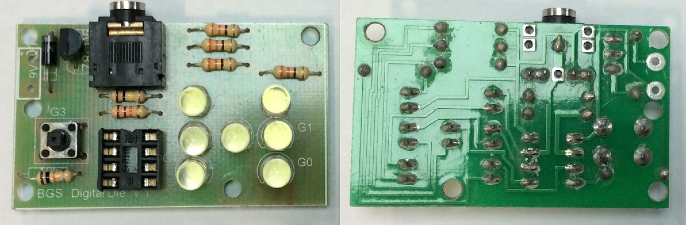
- Board B
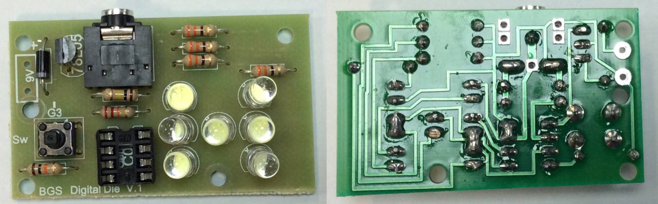
- Board C
- Board D
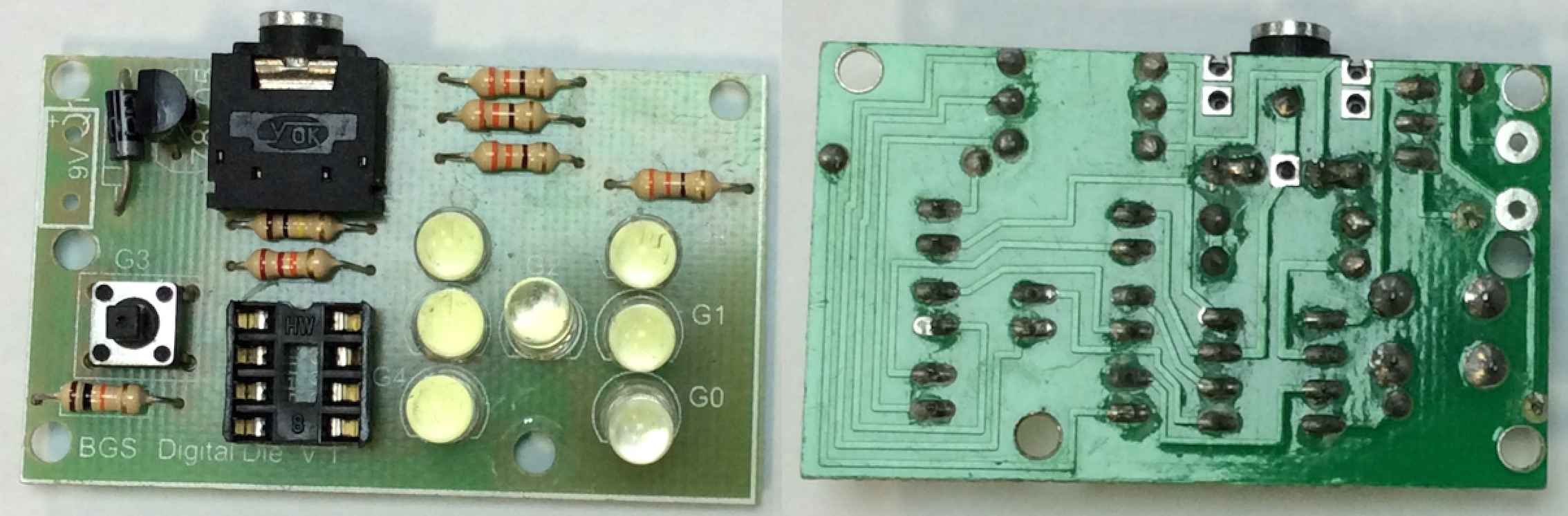
- Board E
- Board F
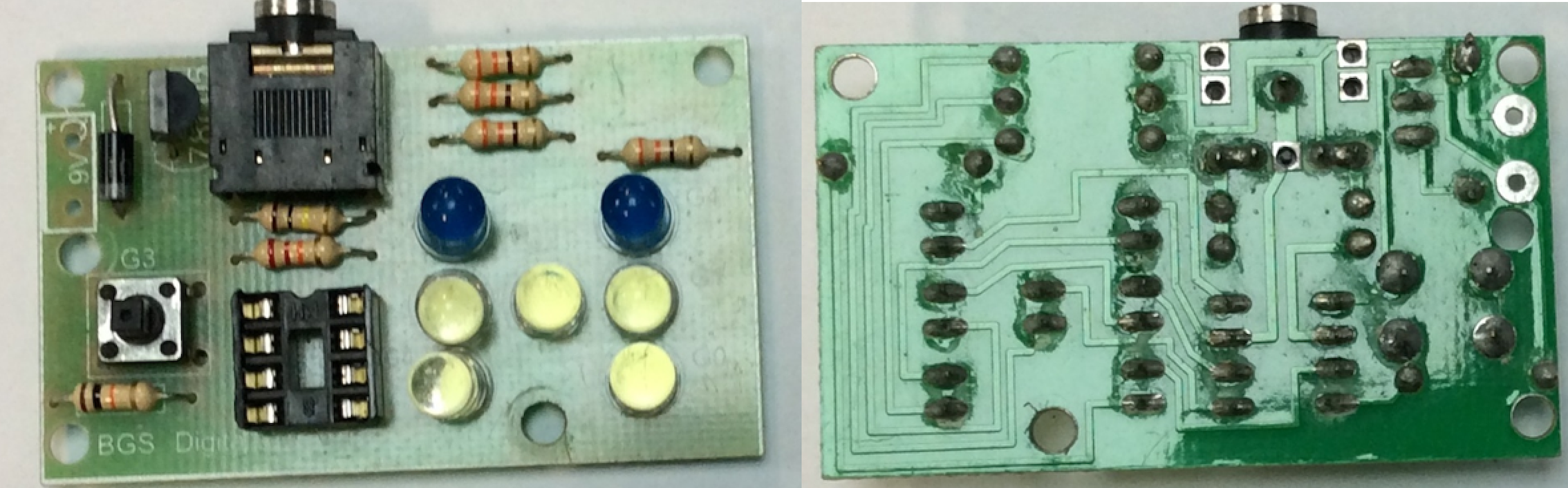
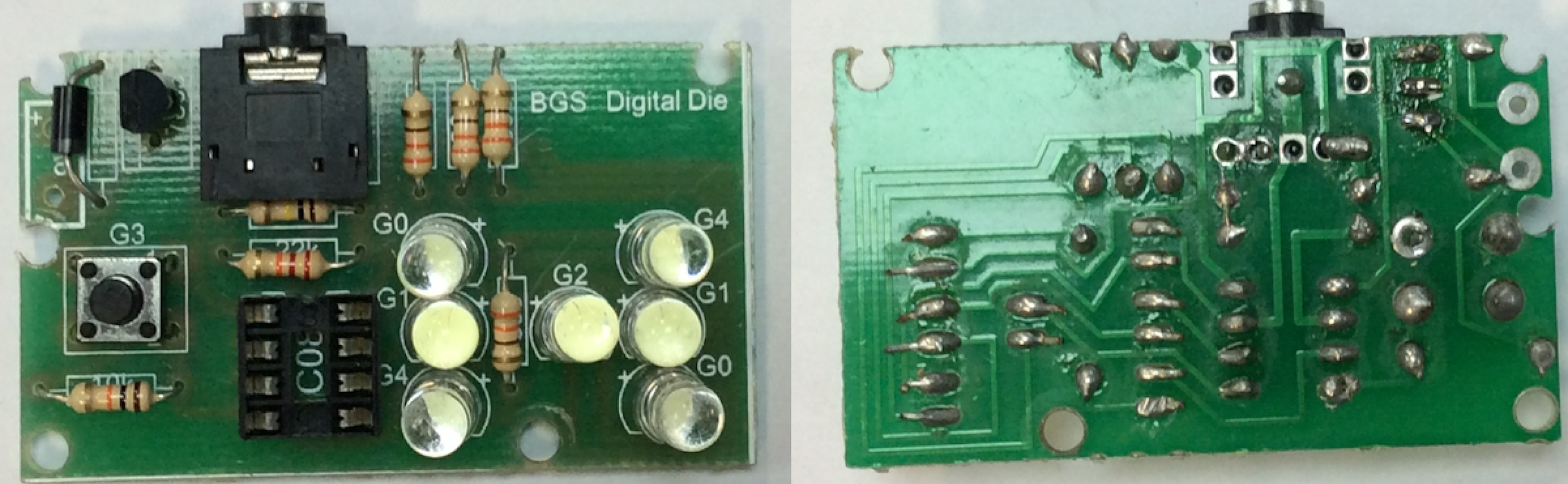
- Board G
- Record your findings in a .txt file called Task 1: Board Faults. The needs to be saved as it will be tested in a quiz once you have completed both Challenge 1 and Chellenge 2.