| Week 1 | Week 2 | Week 3 | Week 4 | Week 5 | Week 6 | Week 7 | Extension Activity | BBL Tasks | Assessment guidance |
The LED Torch - Soldering the board
1 Preparation
Build It
- Soldering the board together should be a fairly quick process, and so long as you have no issues, it shouldn't take more than an hour.
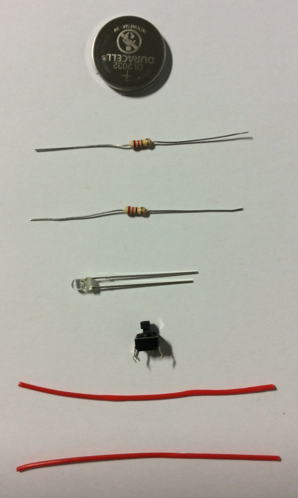
- Firstly you'll need to make sure you have all the correct components.
- You will need:
- 1 x 3V Cells
- 1 x 3Ω resistor
- 1 x Any resistor
- 1 x 3mm White LED
- 1 x 6mm PTM Switch
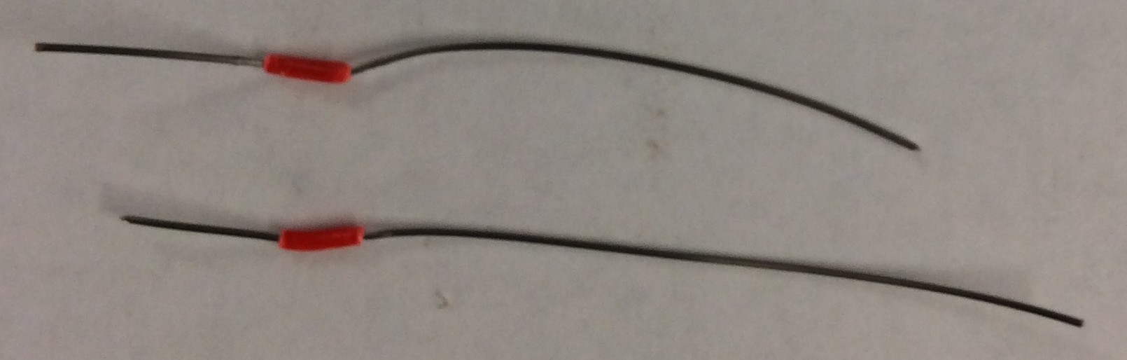
- 2 x 5cm lengths of single core wire (any colour)
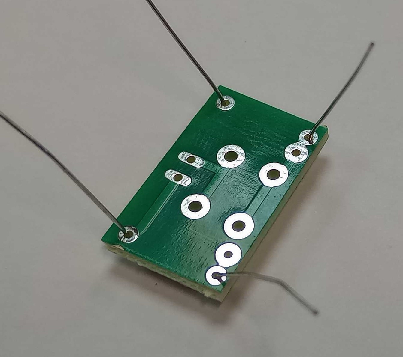
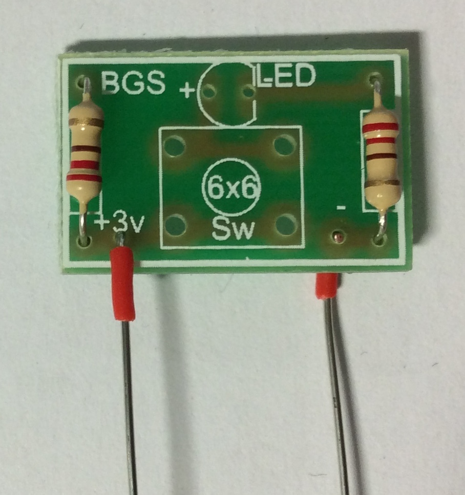
- The board is clearly labelled, to show you where everything is placed.
- This is the side where the components sit.
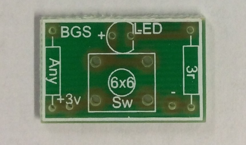
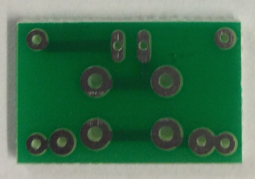
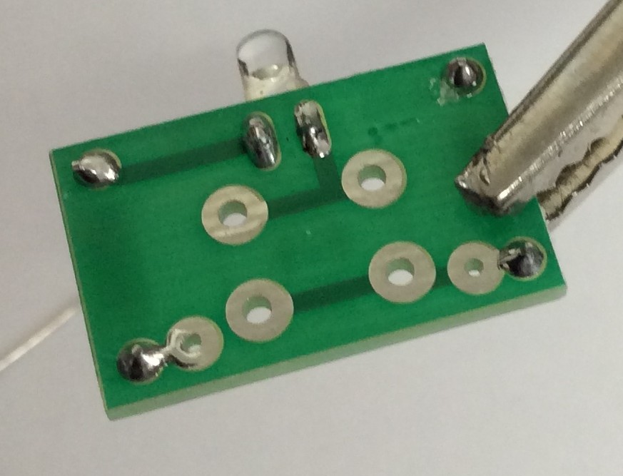
- This is the side where you apply the solder
Build It
- Place you resistors on the board as shown below.
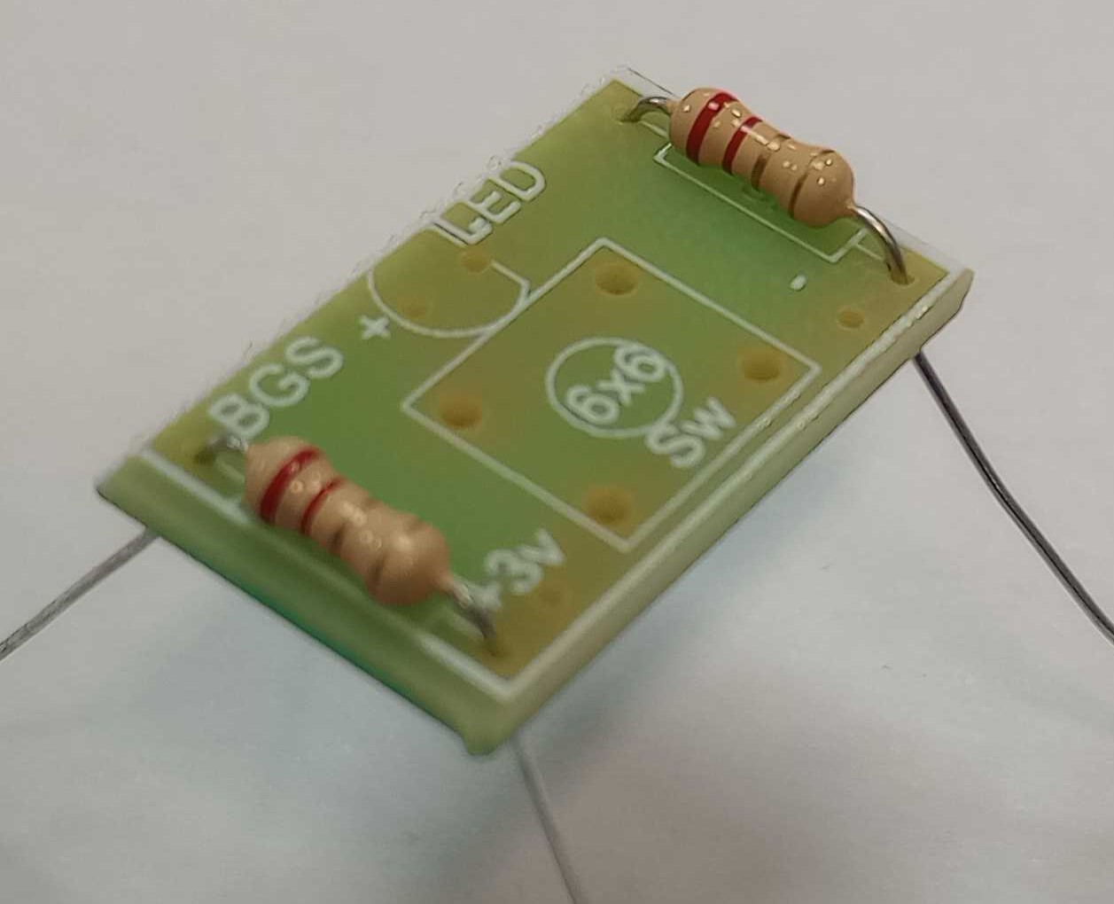
- Then pull the resistor up to the PCB and bend them slightly - DO NOT BEND THEM FLAT ON THE PCB.
- Clamp your board into the bulldog-clip on your soldering iron stand, and make the legs of your resistors stand up as straight as possible.
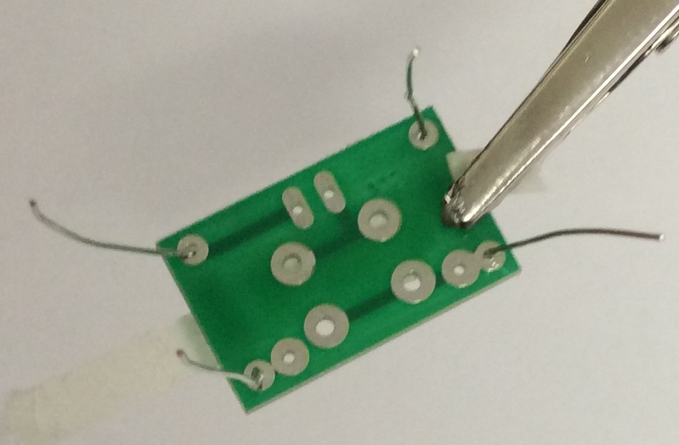
- Then carefully solder each leg in place.
- Hold the tip of the iron so that it is touching both the solder pad and the leg of the component.
- Hold it there for the count of three.
- Feed in the solder so that it melts over the pad and leg.
- Withdraw the solder.
- Withdraw the iron.
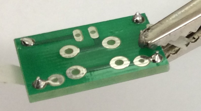
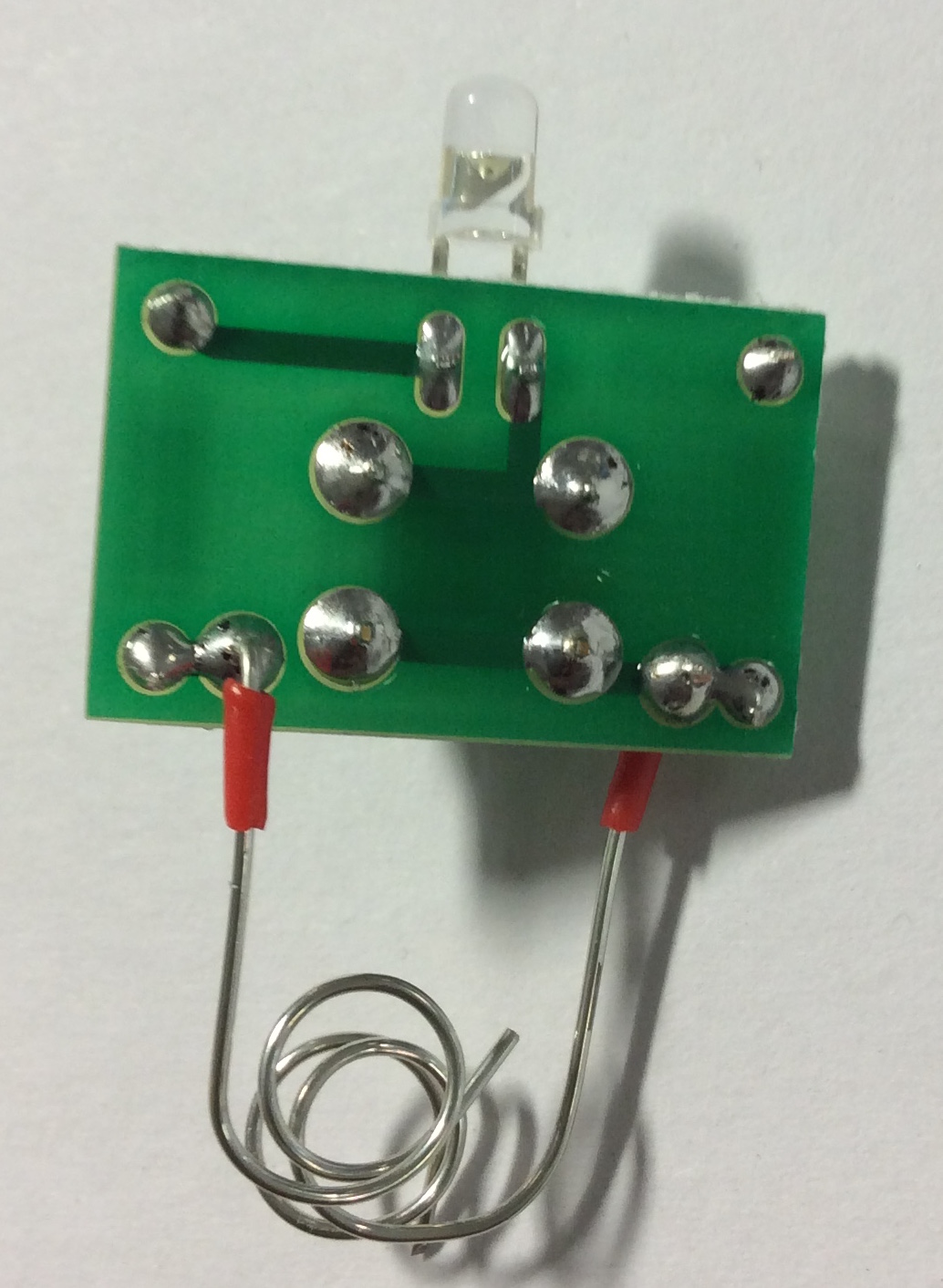
- Use side cutters to trim off the legs.
- Your solder joints should look like this.
- Next we need to solder in the LED. Make sure you put it in your board the correct way around. The long leg goes through the hole marked with a
+.
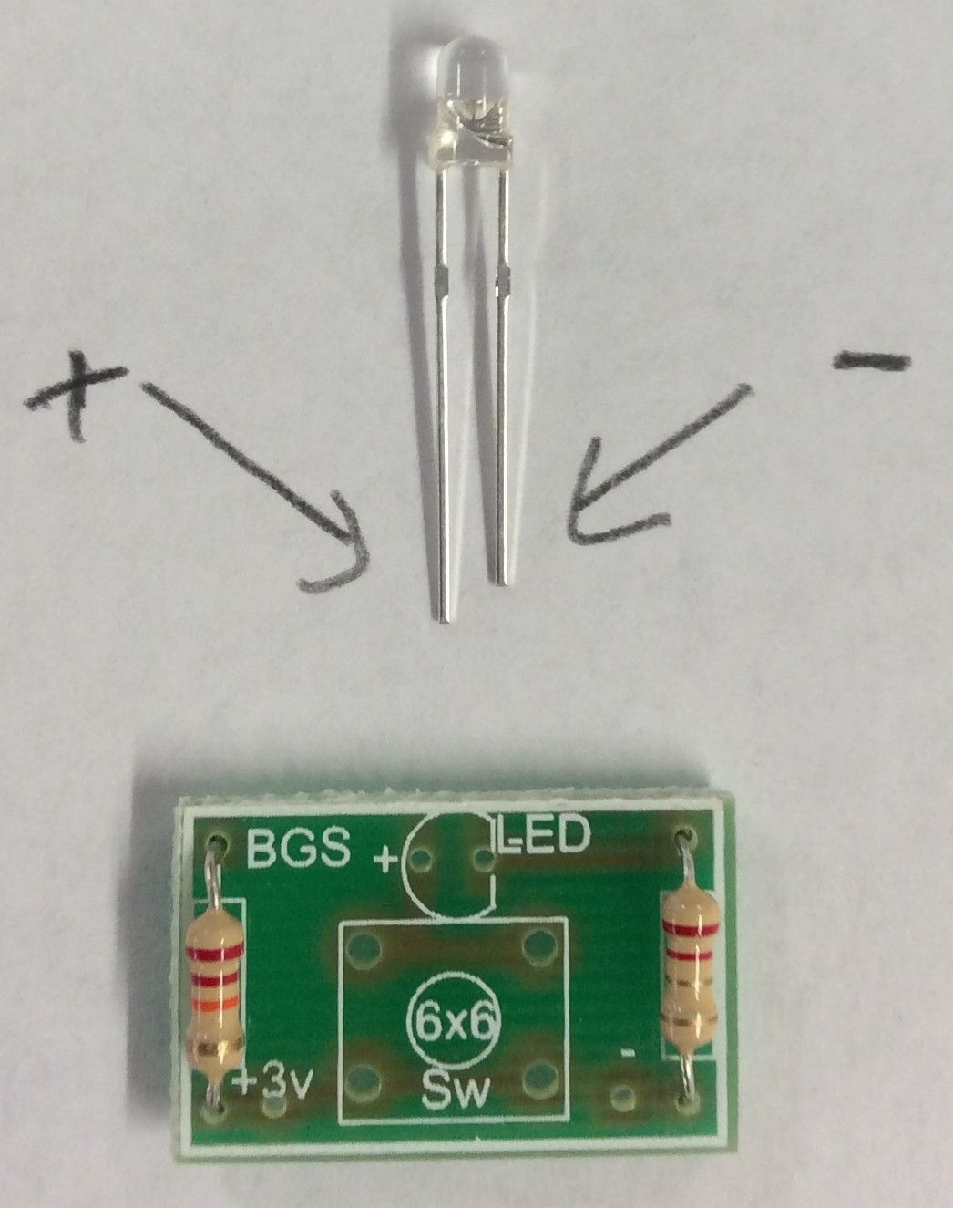
- When you place the LED into the holes, bend it over so that the bottom of the LED touches the edge of the board.
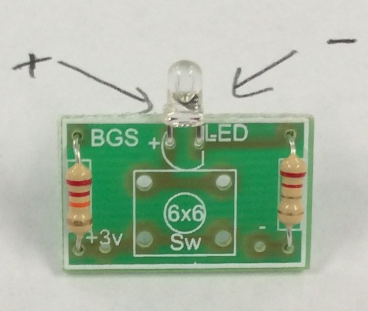
- You may want to use masking tape again, if you feel you need to. Solder the LED in place.
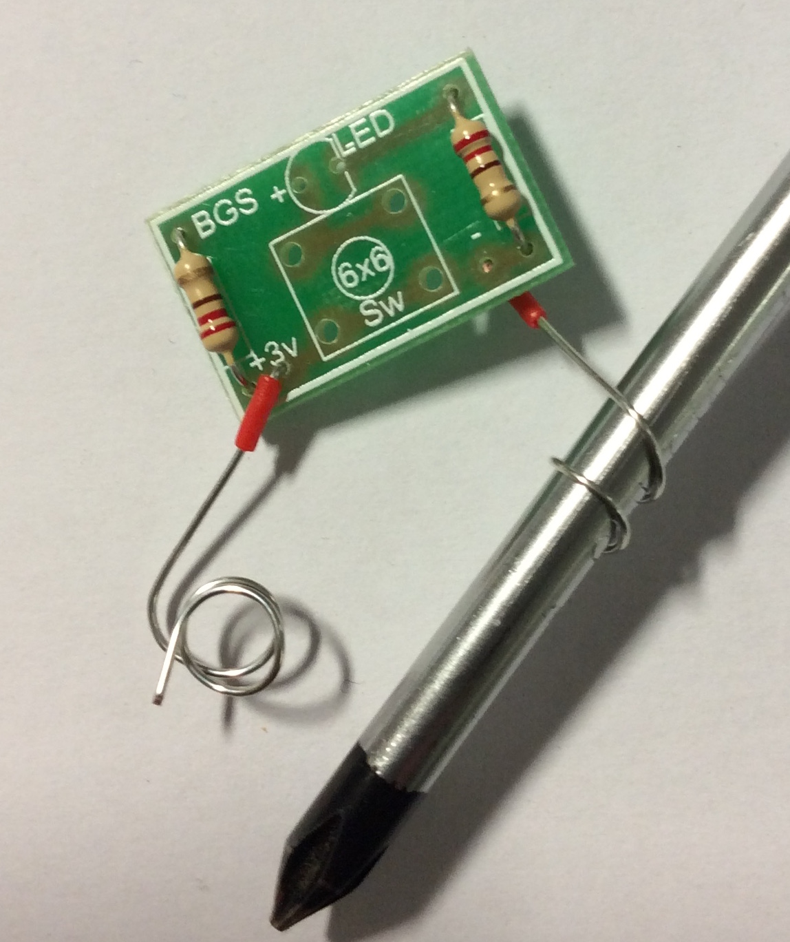
- Next take your lengths of single-core wire and strip off the insulating plastic as shown below.
- Now solder the wire into the board as shown.
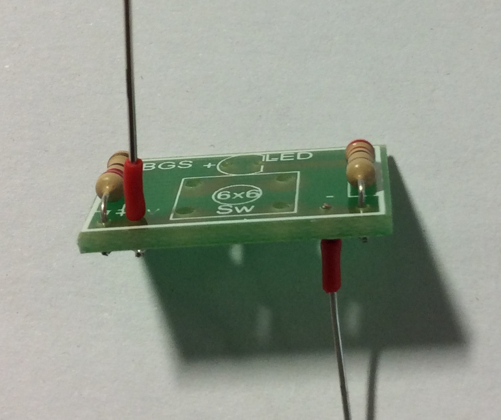
- Make sure the positive wire comes from the top of the board and the negative comes from the bottom.
- Next, use a screw driver to coil the bare wire.
- Our last component is the PTM switch. Use masking tape to keep it in place.
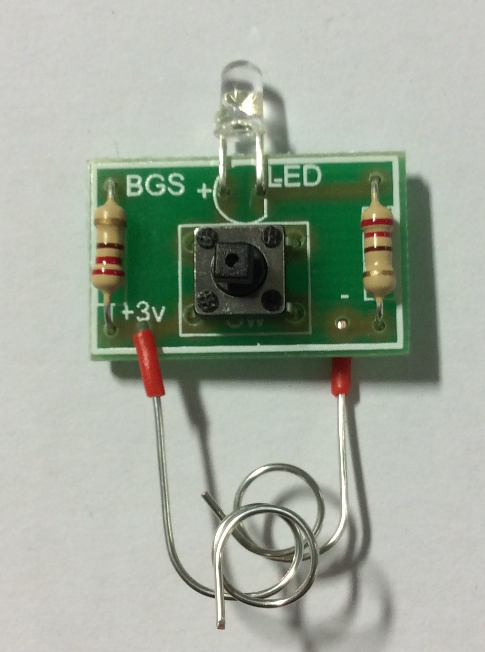
- Then solder it into the board.
2 Assessment
Badge It
Silver - Progress ladder Yellow, Identify and solder simple components (e.g. resistors) to PCBs, with assistance.
Gold - Progress ladder Green, Solder more challenging components (e.g. ICs) to a PCB, with assistance.
Platinum - Progress ladder Blue, Confidently and consistently solder components to a high standard.
- Once you have completed your board, take it to your teacher for testing.
- If it works, take pictures of both the solder side and the component side.
- You will be assessed on the quality of your soldering and component placement.