An Introduction to Mechanisms
1 Modelling the Cam Mechanism
Learn It
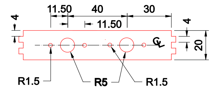
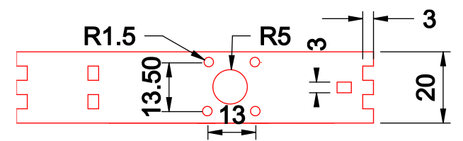
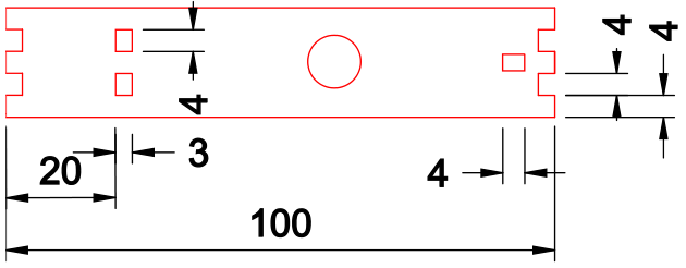
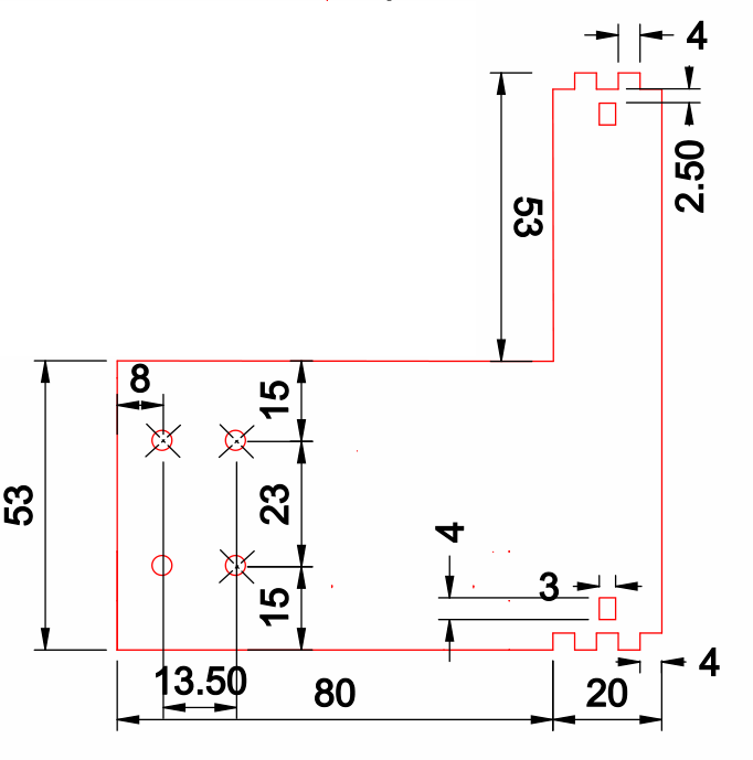
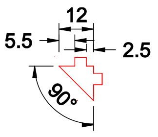
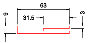
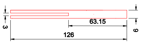
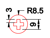
- Below you'll find drawings of each of the parts of the Cam mechanism that you are manufacturing.
- None of the parts are to scale, so read the dimensions carefully
Badge It - Silver
- After creating all the parts in SolidWorks. Upload one screenshot of the follower guide.
- Adapt two of the Cams you have made, so that they have crosses in the centre to fit the axle.
Badge It - Gold
- You are going to create an Assembly of your mechanism.
- First task it to gather the files you need. The other 5 pieces needed are in the Open drive > Design Engineering > Year 7 > 4 - Mechanisms. > New
- Select all the parts > CTRL +A then copy them CTRL + C. Navigate in your folders to your cam box folder and then paste CTRL +V
- These need to be saved into your area before you can begin assembling the frame.
- The image below should help you understand how the pieces fit together.
- Also there is a video to help.
Badge It - Platinum
- Use the animation tools to create an animation of your working mechanism.
- HINT - there is a special type of
mate called a cam mate, see if you can use it to mate your cams to your followers.
- Alternatively use the video at the end on 'gravity and contact' to make it work. You will need to apply the gravity to the followers and the contact between the cams and the shaft end/followers.